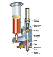
Several parameters can be adjusted to alter the size of the dots produced. The parameter adjustments affect the dots in two ways: by changing properties of the fluid or by changing mechanical properties of the jet. The pressure on the fluid in the syringe was adjusted from 10 to 30 psi. This variation affected how much force pushed the fluid down and around the ball-needle tip when it was raised. The other parameter that affected fluid properties was the nozzle heater temperature setting.
Throughout this article, when reference to temperature is given, the temperature is of the heater setting and not the exact temperature of the fluid. The fluid temperature is always a few degrees less, due to thermal conduction losses in the system. The temperature settings were varied between 30

Theory
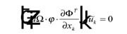
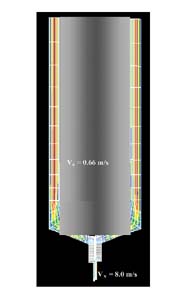
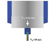
Numerical analysis was performed to simulate the jetting process and drop formation. Incompressible fluid and non-slip theory were assumed in the simulations presented in this article. It was determined that the Reynolds number was very low and, therefore, turbulence conditions were not present. The ball needle was accelerated by the spring and the transfer of momentum into the fluid caused the drop to form when surface tensions were overcome. The set of equations needed to define the problem consisted of the mass conservation equation.2
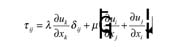
The third expression is the constitutive equation relating the shear stresses to the tensions
Experiment
Perhaps the most important parameter used when evaluating the dots (in addition to the quality, or overall shape and roundness), is the measure of the dots' size. This was accomplished by looking at not only the diameter of the dots, but also by determining their mass and volume. The measure of the dot diameter was often the easiest measurement to make, and was often used as a preliminary estimate of the size and quality of the dots. These measurements were determined using a variety of methods and calculations.Three methods were used to find the diameter. The first and most commonly used was the measuring microscope. This machine is a Panasonic GP-KR222 camera attached to a Nikon microscope, which is fed into a monitor and a Quadra-Chek 2000 measuring system. The dots are focused, then maneuvered, using the adjustable stage so that the left and bottom edges of the dot are lined up with crosshairs on the monitor. The x and y measurements on the Quadra-Chek were then zeroed, and the dot moved until the right and top edges were lined up. The resulting x and y displacements of the stage are accurate measurements of the diameter of the dot in the corresponding directions. The one drawback to this method is that it requires human estimation to line up and measure the dot size, so some variation could occur between measurements.
Another important consideration was the determination of the edges of the dots. Often, depending on the surface, there was a halo around the edge of the dot. This halo had a negligible height, and was therefore not included in the diameter measurements.
The second method of determining the diameter of the dots was using the Cyber-scan profiling machine. By reflecting a laser across the surface of the dot, a height profile is generated. This can not only be used to find the height of the dots, but also, by measuring the extents of the profile, the diameter of the dots can by found. However, the machine could only scan certain surfaces; if the surface was too reflective, the laser could not be focused properly.
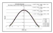
The final method for finding the diameter of the dots was to dispense dots in a set pattern on a polished plate. A camera was programmed to photograph each dot 10 times, in series. These photographs were fed into a computer and analyzed by a program called Sherlock. The pictures were examined for shape, size and consistency, and the results compiled. Once the diameter of the dots was determined, and good dots obtained, the volume of the dots was estimated. This was accomplished four ways: two approximations using the measured height (from Cyber-scan) and diameter (from any method); one approximation used the profile; and the last flattened the dots into cylinders and then estimated their volume. The first two methods assumed a certain profile of the dot shape. One used hemispherical profile (assuming the surface of the dot resembled that of a slice of a sphere) and the other used a profile resembling that of an ellipse. The Cyber-scan was used to determine the height of the dots; the entire profile measurements were exported to a file. Plotting this data and fitting a polynomial curve determined the volume. In this experiment, the dots were zeroed (peak occurs at zero on the x axis) and then fit to a fourth degree polynomial (plots are shown in Figure 6).

Jetting Underfill Results
The first fluid tested was Namics XS8436-79 underfill fluid. This fluid was tested within the following parameters ranges. The preload was varied between three and four turns, and the temperature was set between 50 and 60Jetting Silver Paste Results
The second material that was used to jet dots was a silver paste solution (used in the same manner as silver epoxy), formulated by Superior Micro Powders. Dots were made with an average diameter of 18 mil (0.4572 mm) and were found to have a height of 2.4 mil. Using a polynomial approximation, the volume was calculated to be 0.007 ml, while a hemispherical approximation estimated the volume as 0.0094 ml. By massing a number of dots on a slide, the average weight per dot was found to be 0.056 mg/dot. While this value is higher than the masses of the other two materials jetted, it is a result of the greater density of the fluid, not a larger dot volume. While the volume of the dots ejected was small, the diameter was still rather large, relative to the diameter of the dots dispensed with Loctite SMA-3621. The SMA material has a greater viscosity than the silver paste, and while the volumes of the dots are similar, the diameter of the SMA dots was much smaller (owing to their greater height). With a silver paste with greater viscosity (closer to that of SMA), perhaps dots could be jetted of comparable volume, but, due to the greater viscosity, with a larger height and a resulting smaller diameter.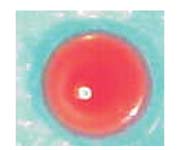
Jetting SMA Results
The third fluid tested with the DJ-2000 Jet was Loctite SMA-3621. This material was the one most tested, and the one jetted at the largest range of settings. During the experiment, the preload was varied from two to four turns and at stroke lengths between 0.12 and 0.75 mm. The valve was left on from 5-7E-2 seconds, and both 4 and 5 mil nozzles were used with 15 and 20 mil seats.
Jetting Abrasive Underfill Materials
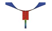
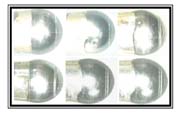
For some time, it has been a challenge to jet abrasive materials consistently for extended periods of time. This is because the materials in contact with the abrasive fluid develop wearout that eventually affects the outcome of the jetted material. Although this occurred with the materials used, the relevant issue is that of the time to affect the jetted material characteristics, including geometry, volume and mass. Hence, one needs to understand the evolution of such a wearout mechanism as a function of actual operation and then determine its field mean life. Figure 11 shows needle wearout evolution resulting from jetting abrasive underfill material, Dexter 4549. One can observe the increase on the area of that contour where the needle meets the seat of the jet by displacing the abrasive fluid present prior to impact.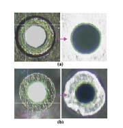

Findings
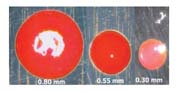
Throughout this study, several general trends were observed. It was found that the parameters that most consistently affected dot size were valve-on-time, seat size, temperature and stroke length. A shorter valve on time seemed to correspond with smaller dots, perhaps because there is less time for material to flow beneath the ball needle. With the jetting process, small dots were made at shorter valve-on-times. In addition to valve-on-time, the new design (smaller jet geometries) resulted in a significant improvement; dot diameter was reduced by 16% without any impact on the dot quality. Because of the consistency of the underfill (similar to syrup or honey), perhaps greater force is needed to separate a drop from the rest of the fluid. Even with four turns of preload, the stroke length may need to be longer to get the required compression of the spring to jet a dot. The final parameter affecting the size of the dots was the temperature to which the fluid was heated. It was found that, by adjusting the temperature and leaving all other settings constant, the dot size was not changed. However, when the fluid was heated to higher temperatures, the stroke length could be set lower before it began to clog. Therefore, with more heat, the stroke length could be set lower, giving smaller dots, so temperature indirectly affected dot size.The other adjustable parameters did not seem to influence dot size quite as much. Pressure was another parameter that had to be balanced. Pressure needed to be high enough to force fluid below and around the ball-needle when it was raised, but also not so high that the pressure to back pressure difference was too large. With a pressure much greater than the back pressure, a greater amount of fluid was jetted with each drop. However, even when varying pressure between 10 and 50 psi, the influence of this effect on dot size was small compared to the influence of other parameters. A final observation regarding the variability of dot size based on parameter settings is the potential benefit. The ability to adjust a few parameters and get dots which range in size from 12 mil in diameter to greater than 30 mil in diameter, along with the ability to fire multiple dots in the same place (to get larger dots), makes the jetting technology an extremely versatile process.
Conclusion
Numerical analysis shows the analytical process for the jetting process and the role of various parameters on the fluid being jetted. Geometric, thermal and mechanical parameters can be manipulated to achieve various size dots. The mechanical and thermal parameters allow adjustments to dot size on a micro scale. Macro adjustments are made through geometric scaling of the ball needle seat and the nozzle size. The ball needle jet geometry is the most crucial component for macro adjustments. The mechanical and temperature adjustments allow dot size tuning and definition of a print window for stable dot generation. Clearly, there is a path for future geometries that will provide even smaller dots in the future. One of the alterations to the jet design that had the largest impact on the dot size was the switch from 20 to 15 mil seats. It is proposed here that a further reduction of the seat diameter may result in yet smaller dot diameters. From analytical work, there are some indications that an increase of the nozzle length may also reduce dot size based on the fact that backpressure is increased. Having established the ability to jet underfill materials in small amounts (less than 0.01mg dots), it is now possible to underfill small die components under a non-contact system with great consistency. Jetting of abrasive materials does cause wearout in some of the components of the jet, but consistency of jetted material, both quality and quantity wise, is not affected significantly. In fact, the fine-tuning of some of the jetting parameters may result in no change of the material dispensed. Above findings open the application field of the jet to cover a much wider variety of materials.Acknowledgement
The authors would like to thank Mr. A.P. Babiarz for his experimental work and data analysis, and Mr. J. Vint for assistance with hardware issues during this study.For more information, contact Asymtek, 2672 Loker Ave. West, Carlsbad, CA 92008.