
Today's leading-edge wire bonders are capable of 35 µm in-line pad pitch in production environments. The manufacturers have overcome wire count limitations by developing multi-tier, staggered pad bonding over active circuitry. At the same time, state-of-the-art wire bonders offer improved overall UPH, with raw wire cycle speeds of over 16 wires per second. This capacity translates into production UPH rates of 10-13 wires per second, including process and indexing time, depending on the type of device and wire count.
In addition, wire bonders have proven to be the most effective in bonding stacked die in 3D packages. Unlike flip-chip technology, wire bonders have the flexibility to handle an increasing number of dies per package.
But no matter how capable wire bonders are in handling ever-decreasing pitch and ever-increasing wire counts, the entire assembly process must be evaluated to ensure there are no barriers to achieving high yields. One of these potential barriers is wire sweep.

The Effects of Sweep
Wire sweep occurs when bonded wires are not correctly aligned in the horizontal plane (as opposed to wire sag, which is in the vertical orientation). Wire sweep can occur during the wire bonding process, during handling after wire bonding, or during molding. Wire sweep is undesirable; it can affect electrical performance by changing the mutual inductance of adjacent wires and SSN (simultaneous switching noise). If the wires touch, they will short (see Figure 1).Proper process development and setup can reduce or eliminate wire sweep during bonding. Automation can reduce the risk from handling. Wire sweep during molding, however, is more difficult to eliminate, particularly with the finer pitch and more complex wiring schemes in today's advanced packages. Wire movement is most often caused when molding materials flow transversely across the bond wires during mold encapsulation. Wire sweep usually occurs near the mid-span of the wire or near the second bond.
Today's advanced package production wire bond pitches are 35-45 microns, with sub 35 microns pitch in development. Smaller wire diameters are used to achieve these finer pitches. At the same time, wire lengths can be longer than 7 mm in stacked-die and die-shrink applications. These fine-pitch and/or long-wire applications are extremely difficult to mold with low-cost molding materials and processes due to the increased propensity for sweep.
Conventional encapsulation materials and processes are not adequate for sub 35 µm spaced wires. In tests conducted by Kulicke & Soffa, corner gate molding was not successful on 35 µm pitch die with 15 µm wire diameter, and 4.7 mm long gold wires. The molding materials and parameters simply moved the wires too much due to the flow characteristics of the materials. The problem is that standard molding compounds are primarily comprised of spherical silica filler. Typically, this filler has an average diameter distribution that can be higher than the gaps between the fine pitch wires. Trying to inject this material through the wires causes wire movement.
Reducing Sweep: The Conventional Approach
Mold equipment makers and mold compound makers have been working for years to develop new technologies to reduce sweep. At the same time, assemblers prefer a solution that uses their current capital assets and limits reinvestment. Any technical solution needs to be cost-effective or it won't be adopted for mainstream use.The move below 45 mm pad pitch has generated a new set of challenges that are stretching the capabilities of conventional processes and materials. Many new mold compounds with lower viscosities and smaller filler diameters are being developed for use in conventional edge gate and new center gate molding processes, but there are significant technical challenges. The materials use smaller average particle size fillers, which increase the compound's viscosity. The increased viscosity, in turn, generates more drag on the wires during injection. Therefore, the higher surface area of the smaller fillers must be offset by lower viscosity resins and slower injection speeds.
Tests with several of these new encapsulation materials at Kulicke & Soffa have demonstrated 10% sweep reduction using edge gate molding to 30% reduction using low-sweep mold compounds. These results were achieved using K&S AW99 wire. Approximately 5% overall sweep was achieved for corner gate molding at 35 mm with low-flow compound in a collaborative test with plastics pioneer Sumitomo Bakelite (Tokyo). Additional improvements can be expected if the assembler is willing to live with lower productivity or higher material costs.
Wire Insulation Technology: Teaching An Old Dog New Tricks
Sweep does no harm if the wires are sufficiently insulated. Insulated wires could alter the way companies approach device design and process engineering. Devices could become far more complex if wire touching was no longer a concern. This capability would be a boon to the rapidly expanding stacked-die packaging market, enabling almost unlimited design flexibility. And the focus of wire bond process engineers would shift rapidly from loop profiles to bond integrity.At least two wire manufacturers offer wire with an insulated coating. This technology, used for a century in magnet wire, has been in stop-and-go development for over 20 years for wire-bonding applications.
While simple in theory, the wire insulating process is technically challenging. The low K coatings on the wire must be applied evenly without affecting the wire bonding process. Therefore, the wire coating cannot: radically alter the looping behavior of the wire; scrape off and contaminate the capillary; chemically disrupt the formation of the first ball bond; or degrade the strength of the second bond. The most developed technology for wedge-wedge bonding avoids ball contamination.
The system costs of using insulated wire are not yet determined. In theory, only a small amount of polymer would be required. However, since the industry has very limited experience coating 15 and 12 mm wire, the cost would be process-driven - both from the wire coating phase and the effects of the wire on wire-bonding productivity.
Less Radical Approach Gaining Favor: A Detailed Look
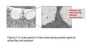
A new, patented, sweep-resistant encapsulant technology offers a unique solution to sweep. This silica-filled liquid polymer developed by Polysciences Inc. easily disperses to encapsulate wires, locking them in place and prohibiting their movement during process transition and transfer molding. The material is dispensed onto the wires immediately after wire bonding, flowing easily between and around the wires without causing sweep, sag (wire in the Z direction), or voids. Quickly jelled with UV light, wires are secured in place so that the device can be handled and molded without damage. Test results at assembler locations show that sweep decreased from 6.5% using conventional molding process and material to only 0.12% using the sweep-resistant encapsulant technology.Another study demonstrated that the polymer encapsulant successfully eliminated existing shorts. Results showed that the properties of the polymer and the small diameter filler particles actually separate shorted wires during encapsulation. The capillary action of the liquid encapsulant wicked between the wires, separating them after the flow was complete, and the compound initially cured on the wires remained separated. Obviously, eliminating or reducing existing shorts can significantly decrease rework and improve overall yield.
Experiments run at Kulicke & Soffa and reported at SemiCon West 20023 demonstrated that using a wire-locking polymer eliminated 80% of existing shorts. Applied in production, this translates to an increased yield from 99.5 to 99.9% (see Figure 2).

How it Works
In simplified terms, sweep-resistant technology is designed to lock the wires in place after wire bonding. Figure 3 shows the process flow on a typical PBGA application.After wire bonding, the encapsulant is dispensed onto the wire-bonded device and solidified by UV cure. Then, just as in a normal process, the device is molded for encapsulation. The sweep-resistant encapsulant is then fully cured along with the molding compound during post mold cure (see Figure 4).

For dispense and cure, there are two options: online process and offline process. With the offline process, the sweep-resistant encapsulant is dispensed and cured with a regular "glob-top" stand-alone dispenser and conveyor UV equipment. Of course, it requires proper temperature, pressure, and speed setting according to the applied package and dispensing pattern. Generally, this is suitable for those processes that need wire rework or repair after wire bonding. Wires can be locked in three to five seconds with UV curing.
The online process is used for high-yield wire bonding applications that require optimal design flexibility and production space utilization. A dispense-and-cure kit installed on the wire bonder allows the encapsulant to be dispensed and UV-cured right on the bonder as part of the normal process. The dispense/cure time normally does not impact the wire bonder UPH, as wire bonding occurs simultaneously with downstream devices that are undergoing dispense and cure. This process is especially applicable to high wire count devices, since the dispense/cure cycle time is typically much shorter than the time required to bond all the wires on the device. Once through this process step, all wires are locked and fully protected from movement. The device is ready for mold - sweep-free - and can be safely handled.
Since the dispense/cure is performed on the wire bonder, additional savings can be realized from reduced floor space requirements, as both the stand-alone dispenser and UV-cure oven are eliminated. Furthermore, as the dispense/cure process program is entered as part of the wire bonding process program through the same interface, assemblers reduce training and learning curves.
Favorable Results Performing in a "Multi-Media" Environment
Once the assembly device is molded, the encapsulant is in the middle of a fairly complex environment where it must interface with a variety of materials, including the molding compound, die, substrate and die-attach adhesive. Developers of the sweep-resistant encapsulant technology accounted for this when formulating the encapsulant material. To maintain reliability and to function well in the process, the encapsulant was formulated with the following key performance properties.- Excellent adhesion
- Unique flow characteristics to enable both complete wire encapsulation and bead-type dispense
- Low modulus to reduce stress from CTE mismatch
- Low moisture absorption
- Minimized CTE for excellent reliability
The sweep-resistant polymer and dispense system are being evaluated in the industry with favorable results. One major assembly OEM reported that its yield increased over 2.5% on a stacked die application. Another major assembler, who is evaluating the material as an enabling technology, found that they could now cost-effectively produce fine-pitch, long-wire device designs, which previously would have produced a yield below 90%. Variants of the sweep-resistant technology have achieved the following results on a wide array of devices and substrates: JEDEC Level 2A - 260°C reflow as well as JEDEC Level 3 at 220°, 240°, and 260°C reflow.
Conclusion
Sweep-resistant encapsulant technology can be used in all wire-bonded applications. It is especially suitable for long-wire, fine-pitch, high-I/O count, or complex wiring applications. Target applications are devices susceptible to wire sweep issues during the molding process, such as laminated packages like PBGA, leadframe QFP, matrix array BGA, cavity down BGA, and stacked die.For more information on encapsulation, contact Polysciences Inc., 400 Valley Road, Warrington, PA 18976; phone (800) 523-2575 or (215) 343-6484; fax (800) 343-3291 or (215) 343-0214; or e-mailinfo@polysciences.com .
