Every year, new people join the various businesses that use mixing machines in their laboratories and manufacturing facilities. What seems obvious to many experienced personnel can be complicated and frustrating to these newcomers. The purpose of this guide is to present a fundamental explanation of the “what, how, when and why” about high-speed dispersers.
What is a Disperser?
A disperser is a type of mixer that is used to rapidly break apart lumps of powdery material, uniformly distributing and wetting them in a liquid. It is also used to dissolve soluble solids in a liquid.Dispersers work on the principle of energy transfer. A disc-type blade is mounted at the bottom end of the mixing shaft and rotated at a relatively high tip speed. (Tip speed is the speed at the outer tip or edge of the rotating disc. Tip speeds typical of dispersers are measured in feet per minute, calculated by multiplying the constant 3.14 times the diameter in feet of the disc times the revolutions per minute of the mixing shaft. The industry terminology for tip speed is peripheral velocity.)
The solids and liquids are drawn into the rotating disc by the suction it creates. This suction usually results in a visible whirlpool from the top of the mixture down to the top of the disc. A similar whirlpool is created below the disc extending from the bottom of the tank to the underside of the disc. The whirlpools are actually two individual vortices, although common industry practice refers only to the visible upper one as the vortex.
When the solid/liquid mixture enters the vortices and is sucked into the high-speed disc, the energy (horsepower used to drive the disc) is instantaneously transferred from the disc to the mixture. This intensively focused energy transfer creates tremendous and immediate velocity changes in the mixture as it progressively contacts the disc.
Think of the mixture as a series of individual horizontal layers descending downward from the top and upward from the bottom on to the face of the rotating disc. As each layer comes into contact with the disc, it is instantaneously accelerated from the slow-moving vortex into the very high speed of the disc and projected outward away from the disc and toward the wall of the tank. The rapid tearing apart of layer upon layer of the mixture is shear force, commonly referred to as shear.
Disperser vs. Agitator
Dispersers and agitators will both mix. Mixers are sometimes compared to pumps; the performance of a pump is usually measured in the horsepower required for its gallons per minute discharge capacity. A disperser is a high-powered, low-volume pump. Considering its substantially higher horsepower per gallon requirement, a disperser is an inefficient mixer.An agitator is a low-powered, high-volume pump; hence, it is an efficient mixer. A typical dispersion application (such as the dispersion of pigment to make paint) requires about 1 HP for every 10 gal. On the other hand, an agitator application, such as thinning the pigment dispersion with solvent, requires about 1 HP for every 100 gal. Although the agitator is the more efficient pump, it does not create sufficient shear to disperse most solids into the liquids.
Moderate-shear dispersers, which operate at about half the normal blade speed of high-shear dispersers, are sometimes used in place of agitators when some shear is required. The discs typically have larger teeth to promote better pumping and require about one-third of the horsepower of a high-shear disperser (but still three times more than an agitator).
A disperser will generate the shear force necessary to rapidly de-lump powders in a liquid. This de-lumping process is called dispersion. The agitator is an efficient mixer, but it typically cannot generate sufficient shear to disperse powders, regardless of how long they are mixed. This is because the forces holding the agglomerates (lumps) together are stronger than the force of the mixer trying to pull them apart. Mixers can do an excellent job of holding dispersed (sheared) mixtures in suspension, but they typically cannot disperse (shear) the mixture.
Disperser Limitations
The limitations of dispersers depend on product rheology. If the product being dispersed is too thick, it will not move freely to and from the blade from the wall of the tank. This could result in dead zones of undispersed materials in the tank. If the material is too thin, there may not be sufficient body to generate tearing between the layers of product as they consecutively contact the rotating disc. Tacky or “sticky” products may also hinder the ability of the blade to generate proper flow within the tank.Proper flow should resemble a doughnut, with the blade acting as the hole. Product should flow in a circumferential pattern around the tank wall while simultaneously rolling inward to contact the blade. This type of flow is sometimes referred to as a doughnut roll. If undispersed particles stick to the walls of the tank or the flow is insufficient to roll the entire dispersion into the blade, a thorough dispersion is unachievable. Without flow, there is no “go.”
Adding supplementary agitation to help feed the disperser blade can extend the operating range of a disperser. This type of machine is typically called a dual- or triple-shaft mixer. It has both a shaft with a slow-moving sweeper blade that passes close to or scrapes the tank wall to promote mass flow, as well as one or more additional mixing shafts with disperser blades to generate high shear.

Disperser Selection
Dispersers are available with single-, two- and variable-speed mixing shafts. Some are directly mounted on top of a tank and are fixed to operate with the blade in only the original mounting position. Other tank-mounted dispersers can raise and lower the blade by several feet (to better control the vortex) without exiting the tank.Another design, perhaps the most popular, places the disperser on top of a hydraulic lift (similar to those used at gas stations to lift automobiles) that is mounted to the floor. The lift enables the operator to raise the blade completely out of the mixing vessel and change to another vessel. This technique uses small portable tanks (up to 500 gal) that can be rolled away on wheels or picked up with a fork truck. Larger stationary tanks are often centered within the arc of rotation from the center of the hoist to the center of the mixing shaft. The bridge containing the mixing shaft at one end and the motor at the other is then rotated from one tank to the next.
Choosing the best configuration of available designs is a combination of functional need and economic justification. An experienced process engineer or consultant familiar with dispersers is a good investment.
The size of a disperser is generally thought of in terms of horsepower. However, some dispersers are dimensionally very large but use relatively small amounts of horsepower. (These are exceptions to the rule.) The horsepower of the disperser is related to the blade diameter and the anticipated load that the blade will create at a given speed and resistance. The resistance is a function of the rheology of the dispersion, as well as its viscosity and density.
As the blade diameter increases, however, the horsepower increases disproportionately. For example, if a 12 in. diameter blade were to draw 20 HP in a non-Newtonian system (viscosity changes with shear), doubling the blade diameter could increase the horsepower demand by a factor of five. That means a 24 in. diameter blade of the same design, working in the same product, would require 100 HP. The larger blade would also pump considerably more, so it would lend itself to working in a much larger tank (perhaps five times the volume) and producing a much greater amount of finished product in the same time period.
Horsepower requirements are interrelated with blade diameter, tank diameter, batch size, rheology, viscosity and density. Variations outside recommended operating parameters usually result in compromises in performance such as poor particle separation, extended dispersion times and a decrease in quality of the finished product.
The ideal tank for most dispersers is slightly taller than it is wide. Dished or bowl-shaped bottoms aid in preventing solids from accumulating in sharp corners associated with flat bottoms. Dished bottoms drain to the center, where a discharge valve can be installed. Flush bottom ball valves welded into the center of the dished bottoms further enhance the ease of discharge and cleaning.
Disperser Blades
The blade is sized based on the flow characteristics of the product and the desired degree of dispersion. The thicker the product, the larger the blade diameter must be in comparison to the tank diameter. Conversely, the thinner the product, the smaller the blade diameter must be in comparison to the tank diameter. This comparison is called the blade-to-tank ratio. Thick products such as heavy, flowable pastes may require a ratio of .5:1. Moderate products like paint require a .33:1 ratio, and thin products like stains can work with up to a .125:1 ratio. For example, if the blade-to-tank ratio is .33:1, and the tank diameter is 6 ft, the blade diameter would be 2 ft.Once the batch formula has been process optimized, the typical time required to reach maximum dispersion should range from 20-30 minutes after the last ingredients have been added. Longer times do not usually result in better dispersions; in some cases, they can be detrimental because of the higher batch temperatures generated by the high-shear disperser blade. As the blade begins to wear, increasingly longer batch times are required to get to the optimized dispersion standard. Saw-tooth disperser blades should be replaced once the blade tips are worn to half their original height.
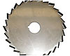
High-shear disperser blades are available in a range of styles and sizes, and can be generally categorized into two groups: open saw tooth and ring type. Both categories work well when used under the proper operating conditions.
The open saw tooth blade is the most popular because of its low cost, ease of cleaning and general utility. It is available in a range of tooth designs. As the teeth increase in size and become more aggressive in shape, the pumping ability of the blade increases. However, as pumping (turbulent flow) increases, shear decreases. A high-pumping saw blade still generates significant shear compared to a low-shear paddle blade agitator. This aspect is an important consideration when determining exactly what is to be achieved in the finished product.
The ring-type blade is a powerful tool for optimizing disperser performance. It is more expensive to purchase and consumes more horsepower than the saw blade. It typically runs at higher tip speeds (5700+ fpm) and performs more like a rotor stator. Instead of solely depending on the face of the disc and the configuration of the saw tooth for shear and flow, much of the ring blade’s work is achieved hydraulically as centrifugal force presses the product between the contoured rings, which creates velocity differentials and a high-pressure zone. The product then instantaneously discharges into the low-pressure area outside the rings, creating a film-splitting Venturi effect.
Additional heat is created as a by-product of the higher shear. In some cases, however, this higher shear level eliminates or greatly reduces any subsequent milling that may have previously been required.
Additional Considerations
Formulating for a disperser is an important part of reaching optimum dispersion. Optimizing a formula can sometimes rely on how and when ingredients are added, since basic recipe changes may not be acceptable. In most instances, the rapid addition of about half the total amount of powders into the liquid vehicle is acceptable, although careful observation of each initial formula is prudent to ensure powders are not floating on top of the batch for more than a few seconds. Adding dry powders too rapidly can “choke” the blade and may result in an incomplete, unstable dispersion.The second half of the powders should be added progressively more slowly until the final percentage completes the formula. The blade speed should be adjustable from a minimum of half the final tip speed at the beginning of the powder addition to the maximum of the final tip speed as the batch thickens and flow slows. This procedure helps prevent splashing and over-vortexing, which are inefficient for dispersion and can cause excessive air entrapment in the dispersion. Assuming the rules of tank size, horsepower, blade size, etc. have been followed, most dispersions are completed within 20-30 minutes after the last of the powders have been properly added. Continuing the dispersion process beyond that time is usually unproductive and can actually cause harm to some ingredients if the temperature continues to rise.
Typically, dispersers perform best when the flow pattern is doughnut-shaped and the blade tips are traveling at about 5000 ft/min in a medium viscosity (1500 to 5000 centipoises). Lower tip speed may be acceptable at higher viscosities and higher tip speeds may be acceptable at lower viscosities to achieve the same shear rate and stress.
Optimum performance requires the following criteria:
• A clean tank
• Correct blade-to-tank ratio
• Proper formulation
• Suitable blade in good condition
• Highest appropriate blade tip speed
• Correct tank geometry (length compared to width)
• Sufficient horsepower
• Proper raw material addition technique
• Proper rheology
Safety Measures
The disperser is a very fast and powerful machine. Serious and fatal accidents can occur in a split second of carelessness. It is important that operators read the operation and safety instructions supplied by the manufacturer. If these instructions are not available, call the manufacturer and request additional copies. Be certain that all operators are properly trained on the disperser’s use and drilled on the potential dangers involved.Do not operate the machine unless all of the appropriate safety features are in place and functioning properly. On hoist-mounted units that raise and lower the blade, these features include but are not limited to the mixing shaft guard, the tank holder with a limit switch, and a limit switch on the lift to prevent the machine from operating with the blade or shaft within reach of the operator.
For additional information, contact Hockmeyer Equipment Corp. at 6 Kitty Hawk Lane, Elizabeth City, NC 27909; phone (252) 338-4705; fax (252) 338-6540; e-mail sales@hockmeyer.com; or visit www.hockmeyer.com.
