
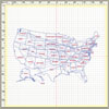
Figure 1. Laser Cutting Software without Optimization
Recent advances in laser cutting technology, especially those that relate to the sophistication of the software engineering behind the laser cutting controls, have created improvements in the type of outputs that can be expected from laser cutters. Today’s lower cost laser cutting systems made from less expensive components have far superior capabilities to the expensive systems that were designed and engineered only a few years ago. At the top end, state-of-the-art laser cutting systems can consistently cut more intricate designs in a wider range of substrates and with tighter tolerances than ever before.
The challenge to those making investments in laser cutting technology is to source machines that are well-matched to application requirements. One can still find laser cutting systems in the marketplace that force compromises in quality or production output that should not be brooked in light of the engineering advances in laser cutting technology. On the other hand, those with more straightforward application requirements are often well-served by lower cost models of laser cutting systems that are powerful and versatile enough for the jobs at hand.
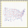
Figure 2. Optimized Laser Cutting Software
A Viable Option?
One preliminary step to sourcing the right laser cutting technology is to first determine if laser cutting capabilities are a good addition to your finishing department. Laser cutters can offer numerous advantages over tool-based die cutting systems. Most of these benefits derive from the tool-free nature of laser cutters, which results in zero tool costs and no production delays for the time required to make the tools.Laser cutting systems are called digital die cutters because they can take any vector-based digital image and import it into their operating software to set up a job. Today’s best-in-class laser cutting systems can complete setup from these imported digital images in just a few minutes. The term digital die cutter speaks to this advantage, especially when used in combination with digital printers. This combination allows users to move from artwork to finished product in just a few hours, or even less for very short runs.
In tool-based mechanical cutting, intrinsic limitations result from the physical contact between the cutting edge and the material being cut. Laser cutting systems bypass that situation, making them an option for many materials that are difficult or impossible for tool-based cutting systems to handle. For example, cutting adhesives is far easier with laser cutting systems because of the adhesives’ tendency to literally gum up the works in mechanical cutting systems. Similarly, the ability of tool-free laser cutting systems to reliably handle thin substrates is a big advantage. In these applications, cut-to-print registration is not constrained by the physical limitations of weighty dies interacting with flimsy substrates.
The relative ease with which laser cutting systems create special features such as perforations, score lines, kisscuts, consecutive numbering, creasing, personalization and others is also a considerable advantage. This is especially the case with today’s laser cutting technology, which uses superior software engineering to precisely control the movement of the laser beams. In fact, the only relevant physical limitation in laser cutting systems is the width of the laser beam. In 350 x 350 mm working fields or greater, for example, the spot size can be as small as 210 microns in best-in-class systems.
While any die-based cutting system would have difficulties in producing corners that are less than 30°, this is not challenging for a laser cutting system. Laser cutting technology also allows users to skip the step of creating mechanical knicks to facilitate parts extraction, as is typically required with a tool-based cutting mechanism.

Figure 3. Sample Operator Screen
Misconceptions and Limitations
While laser cutting systems do have some drawbacks, major misconceptions exist about their limitations. In some quarters, laser cutters are considered to be prototyping tools that cannot handle the requirements of full production runs. While laser cutting may be slower than platen presses, rotary die cutters or optically registered gap presses in many applications, today’s laser cutting systems are considerably faster than their predecessors. In fact, most users of today’s laser cutting systems are using them for full production line capabilities with line speeds of 30-100 m/min.Today’s laser cutters are generally galvanometer-type lasers that make minute adjustments in mirror angles to move laser beams around artwork. This galvo mechanism is considerably faster than gantry systems with XY plotters that physically move the lasers or the sheet of material being cut, not just the laser beams. Newer galvo technology takes this speed improvement to the next level by fine-tuning software to shave milliseconds off of most operations, with a combined effect of significant speed improvements.
In most applications, higher laser wattage results in faster cutting proceeds. The difference today is that faster 200- and 400-watt lasers, which were prohibitively expensive five or so years ago, are now available at competitive prices. These new lasers also make a higher quality laser beam, which in turn ensures that cutting quality is maintained even at higher cutting speeds. The upshot of all these combined speed improvements is that today’s laser cutters can handle far more than prototype samples; they are used for full production runs without creating production bottlenecks. (Note: Manufacturers’ claims on linear cutting speed are not meaningful in most instances. Actual cutting speed is determined both by the complexity of the artwork and the ability of the control software to optimize cutting in that geometry.)
Another common misconception is that laser cutting is a dangerous operation that burdens a workplace with safety risks. Though it may seem counterintuitive to some, laser cutting systems are in many ways a safer alternative to tool-based cutting systems. Care should be taken in the initial installation of a laser cutting system to eliminate the chance of stray beams creating workplace hazards if workers do not wear safety glasses. Tool-based systems, on the other hand, pose a continual risk of severe worker injury if they are not operated properly. Although such accidents are rare, they can be catastrophic. Costly injuries to tooling, such as when technicians inadvertently leave tiny screws in a cutting area that destroy the custom tooling, are somewhat more common.
While it is true that laser cutting systems cannot handle all substrates, the boundaries of that limitation continue to shift as the engineering of laser cutting technology improves. For example, polycarbonate substrates used to be beyond the reach of laser cutting technology because of the laser cutters’ tendency to leave poorly cut edges with a heavy brown discoloration on the substrate. This is still true of the thickest polycarbonates, but not so with the thin polycarbonate substrates that older systems couldn’t tackle. Many still think that polyvinyl chloride (PVC) is not a good match with laser cutting technology, but that is not the case. It is possible to cut PVC materials as long as additional components are added to protect the existing machine components near the laser beam from the corrosive action of PVC cutting byproducts and that appropriate filtering systems are added to protect operators from noxious fumes.
The real disadvantage of laser cutting technology-and the reason that most companies that use laser cutters do so in conjunction with one or another tool-based cutting system-is that it is less cost effective for many relatively straightforward long-run applications that are not beyond the reach of mechanical cutting. Tool-based cutters often prove the better finishing tool in applications where part geometries are easy for a physical tool to achieve; the substrate is not too thin, sticky, abrasive or in some other way troublesome for a physical die; and especially when it involves a relatively long run where the cost of the die becomes a negligible factor.

Soft marking eliminates burn-through problems while making the sharp angles required.
Quality and the Soft Marking Standard
Laser cutting systems that were engineered just a few years ago were often not up to the challenges of cutting complex designs, especially when the artwork geometry included many sharp angles. One can still find inferior laser cutting systems being sold today that are similarly plagued by the quality problems usually evidenced by pinholes at the start and stop of cutting sequences or burn-throughs.For example, less sophisticated laser cutting machines can have trouble whenever turns are required in sharp edges. Telltale black burn-through marks at turning points show where the lasers lingered too long in that spot. One might think of the analogy of a car decelerating when making a turn. The deceleration of the laser beam is sometimes so pronounced that it burns through at critical turning points.
Older laser cutting machines can also experience the opposite problem when they are accelerated in an attempt to avoid burn-throughs. If the control of the acceleration is inadequate, the corner’s edges can become rounded. In these instances, the laser beams are moving too fast to make the sharp corner details.
Improvements in the software engineering of today’s better laser cutting machines obviate these historic quality problems. Soft marking, where the laser movements are better synchronized with artwork geometry and tightly controlled during the entire cutting sequence, eliminates the burn-through problems while making the sharp angles required.
More consistent cut-to-print accuracy is also afforded by the new level of systems integration in the best-in-class laser cutting machines. For example, earlier systems had no way of compensating for the rotation in the working field that can occur as the web moves through the laser cutting machines. Today’s best-in-class systems not only use high-resolution cameras but also integrate the camera information with the laser software that controls the cutting. As the camera systems determine any XY offset values, they communicate these to the laser control software, which is adjusted accordingly. If a laser cutting machine does not integrate inputs from a camera system to the laser cutting controls, it does not have a way to make needed corrections. Tight systems integration where one component (the camera) communicates with another (the scan head) is key to higher quality output.
The quality of the laser source itself also has a bearing on the cutting quality. Better lasers with smaller spot sizes (e.g., 210 microns) facilitate crisp cuts, assuming the control software uses advanced algorithms to move the better shaped and smaller sized beam along. Higher quality lasers, combined with advanced laser control software, also avoid the excess heat that can literally muck up the works in label applications where excess heat can melt adhesives onto release papers, making it difficult to automatically remove labels from the release papers in subsequent production steps.
The type of laser tube a system uses (e.g., open or closed) also affects how the laser can be controlled and how cut quality is affected. Although open, unsealed lasers are getting better in quality, they are still rarely up to the demands of many applications due to several intrinsic problems. Carbon dioxide (CO2) is usually one of several gases in a laser tube, with helium, nitrogen and hydrogen making up the balance. The proportion of each of these gases in the mixture affects the laser power. This ratio is apt to shift in an open laser tube design, where there is a requirement to frequently change one open laser tube CO2tank for another. This makes it is nearly impossible to save settings because there is almost always a difference in gas mixture ratios from one CO2tank to another. These shifting ratios affect how the laser powers and the quality of its cut. To achieve the same quality cut, the operator will need to make adjustments every time they switch tanks; even then, there will likely be variations.
In contrast, sealed laser tubes are not as likely to change in gas ratio composition and only require replacement every 10,000+ hours of operation. This translates into an increased ability to control cutting and achieve a consistent result.
Cutting Speed vs. Web Speed
Today’s laser cutting systems are faster for a variety of reasons. One is that higher powered lasers that cut faster are more affordable, such that most users of laser cutting technology today opt for 200-watt+ systems. Secondly, the more sophisticated algorithms used in today’s better quality laser cutting machines are able to shave milliseconds off of each cutting operation, which cumulatively result in faster cutting speeds. The third and most important reason is that they are able to better optimize the cutting sequence to achieve much faster web speeds.Figures 1 and 2 illustrate the impact that optimized software can have on web speed. In each figure, the blue dotted lines show where cutting has stopped while the laser repositions for a next cut. In Figure 1, no software optimization was used; the path follows the lines of how the vector-drawn image was first created in Solidworks or equivalent software. This non-optimized cutting sequence is so slow that the web would only be able to advance intermittently.
In Figure 2, we see that software optimization has resulted in a significant improvement. The resulting improved web speed is determined during the setup of the job, before it is run.
A second step in web speed optimization can be achieved by splitting a single image into two separate images, and then optimizing the web speed for the split image. The software can tell the operator whether it is best to cut the geometry as a single image, two images, four, etc. Today’s better laser cutting technology can seamlessly stitch these multiple images together.
Obsolete models of laser cutters that can only optimize cutting for cutting speed, and not web speed, restrict the sizes of pictures to be cut to no larger than half the size of the working field. The more sophisticated software algorithms in today’s higher quality systems also provide the ability to continuously laser cut pictures that are longer than half of the working field. The same algorithms that optimize for web speed also eliminate the need for up to 90% of the hard cuts and quality issues that arise when two images are stitched together. They do this automatically, in contrast to obsolete models of laser cutting machines that require operators to manually reset the cutting sequence to avoid hard cuts in the artwork.
Systems Integration
A laser cutting system’s degree of systems integration can largely determine how user friendly it is to operate and directly relates to its potential efficiency. For example, older systems required users to obtain a separate camera system. In contrast, today’s better quality laser cutting systems include cameras fully integrated with the laser software. Operators do not have to learn the setup of a separate camera system, as this is now done directly from the laser control software.Systems that feature full integration of all components work seamlessly with variable images from digital printers. These laser cutter systems enable users to create laser jobs with multiple pictures in different geometries and step-ups.
Systems integration also allows today’s high-quality cutters to automatically compensate for variations in prints, such as those that are created by shrinkage as inks dry. Since the machine controller communicates with the camera system, these cutters automatically account for variations in step-ups from one part design to the next. The laser software and the machine controller are self-calibrating and operator input is not required to measure or input step-ups.
In addition, today’s systems are capable of varying the job stop criteria by part count rewound, rewinder diameter, or the rewinder roll length (see Figure 3). The software that controls inputs, outputs, and the laser cutting each work in concert and communicate fully with each other. Smart stop systems monitor all possible fault conditions, such as web breaks and off-positioning of the dancer arm, or full rewinder rolls. When a fault condition occurs anywhere in the system, it pauses and the error message is displayed on the operator screen. Such smart error messaging facilitates maximum throughput.
Systems integration also facilitates quick and easy setup of repeat jobs. All of the required machine parameters for a specific job (e.g., web speed, dancer arm pressure, camera system settings, etc.) are saved in one file. At the very start of the job, users can achieve the required cut-to-print accuracy without having to reload parameters for different system components separately.
Estimating production time can also be automated by the cutting machine’s software, which creates a database that stores laser settings for various types of cuts (e.g., kisscuts, creases, etc.) for the particular substrate being cut. Using this data, the software calculates the optimum web speed and the potential production rate. This job simulation is done by the software before the job is run, providing users with the ability to make accurate cost projections of new job runs.
Selecting System Components
Users can expect a cost difference of up to 20% between laser cutting systems made from high-end components and those that are made with components of lesser quality. It is important to know that your source for laser cutting technology is not married to particular component suppliers. Best-match components for particular applications (e.g., laser source, laser scan heads, etc.) can be sourced worldwide. Lower cost systems can produce high-quality outputs if the underlying software engineering and systems integration are up to par.Knowing the real quality requirements is the first step in determining whether an operation is better served by low- or high-quality laser cutting systems. While most users will be adequately served by lower cost systems, quality baselines that should always be achieved include avoiding burn-through marks and ensuring a crisp, narrow cut that precisely follows the artwork geometry. A laser cutting machine must have a high-quality laser source with a small spot size to achieve these results. In label applications, this also allows for much better control of the heat transmitted to the release paper on the back of labels.
Inferior laser sources with larger spot sizes often make it difficult to remove the cut labels because melted adhesives cause the labels and release paper to stick together. If a laser cutting system presents burn-throughs, it usually reflects poor-quality engineering software and an inferior laser source with a large spot size. The soft marking capabilities of today’s better quality laser cutters should be considered as a non-negotiable feature, whether a system is high- or low-priced. Systems at all price levels are capable of achieving this level of quality, though not all of them do; thorough investigation is required.
The wattage of the laser should be carefully considered. Many of the commercially available lasers achieve the best laser beam quality with full power. If an application requires only 10% or less of the laser power from these laser sources, users can expect significantly diminished laser beam quality. In these cases, a converter making kisscuts with easy-to-cut materials that has a 300-watt laser in their cutting system may be using only a small portion of available laser power and would be better served by a lower watt laser. In contrast, a converter making many throughcuts (including more difficult-to-cut release paper) who also wants to achieve high cutting speeds would need that 300-watt laser.
The edge quality that a particular laser cutting system delivers varies with the spot size of the laser. A smaller spot size leads to better cuts because the energy is concentrated and less laser power is needed to achieve the same depth of cut. In systems with smaller working fields (e.g., 200 x 200 mm field size), this is not much of an issue and one can expect both the better high-end and lower priced systems to have a 210-micron spot size. If the working field is larger (e.g., 300 x 300 mm field size), however, one needs to be able to make due with a 280-micron spot size when considering the lower priced system. Higher priced systems will be able to hold a 210 micron spot size with a 300 x 300 mm working field. As an example, generic label converters might be well-served by a system with such larger spot sizes, while those involved in RFID applications might need the greater precision in cutting edge quality.
Smaller spot sizes also affect cutting speed. It is important to verify that a system can maintain the desired edge quality and cut-to-print accuracy at the system’s maximum cutting speed. Some of the more poorly designed laser cutting systems cannot maintain cut-to-print accuracy over time. Low-cost laser cutting systems may use sensors for registration, or, in more demanding applications, sophisticated camera technology to deliver the tight tolerances in cut-to-print registration that are typical of high-end systems. If the camera systems are fully integrated with the laser scan heads, they can apply the offset values to keep cuts to a precise registration. It is not only the quality of the camera but the underlying software engineering that has great bearing on the tolerances that can be achieved at varying speeds.
Features that affect ease of operation are found in low-priced and high-end laser cutting machines alike, reflecting the high level of systems integration in better quality laser cutters at all price points. Smart stop systems; job simulation software; automatic image splitting; and optimization for web speed, variable job stop criteria, bar code reading for on-the-fly changeover, and one-step job setups of all operating parameters make these systems straightforward to operate, even for lightly skilled workers. Because the software automatically handles most of the system’s operations (e.g., registration, web control, laser powering, laminating, slitting) and because the different system modules communicate with each other, the operator’s work is relatively simple.
Obsolete technology does not provide these various features for ease of operation. Some out-of-date designs do not even give operators the capability to change job settings while the laser cutting machine is operating. These types of laser cutters, which force operators to stop cutting operations entirely and reload a job from scratch, saddle users with unnecessary drags on production. Today’s better quality laser systems bypass these obstacles by giving operators numerous methods of amending job parameters without shutting down the production line.
For additional information, contact Spartanics at 3605 Edison Place, Rolling Meadows, IL 60008; phone (847) 394-5700; fax (847) 394-0409; e-mail sales@spartanics.com; or visit www.spartanics.com.
Editor’s note: This article is based on a white paper entitled “Technical Guide: How to Match Today’s Laser Cutting Technology to Application Requirements” and has been excerpted with permission.


