Material formulators continue to define and develop new formulations of epoxies, silicones, polyurethanes, and acrylics for their customers’ product assembly
| Jump to: |
applications. These formulated materials use raw chemical materials and additives intended to meet new customer requirements or formulations for entering new market applications.
Once these new formulated materials are developed in the lab and appear to be ready to test, a material batch is developed to simulate use by a customer who is assembling a product. The customer application may be bonding, sealing, potting, encapsulating, gasketing or molding. The customer’s material dispensing process may be extruding, spraying, streaming or swirling the formulated material onto or into the product. Since many different development paths are available—along with fewer paths to success for the material formulator—it is important to define the focus applications and test the material batches in closely defined real-world examples.
One of the more difficult materials developed by material formulators is a two-component adhesive or sealant. These are referred to by customers as two-part epoxies, silicones, polyurethanes, acrylics, polysulfides and hybrid materials. The difficulty of formulating two-part materials is in the additional number of variables required to define the success of the new material formulation. These two-part materials have two different chemistries that are combined and mixed at a specific ratio, with a narrow ratio tolerance, at a certain viscosity, for a certain volume, and with one or more cure time ranges. One or both chemistries are varied, and this process is repeated until a material batch is created for testing in a dispensing system.
Two-part dispensing equipment in the material formulator’s lab is used to test new two-part materials. The ideal method is to simulate the focused customer’s dispensing application and process using the same or similar dispensing system. This may or may not be possible since there is a wide variety of applications and processes. To get close to a simulated application, a material formulator may need a variety of metering units, supply units, mixing valves and accessories (e.g., including temperature control, sensors and measuring devices) to test a formulation in a dispensing application. This can be expensive and time consuming to assemble, and the equipment requires storage space when not in use.
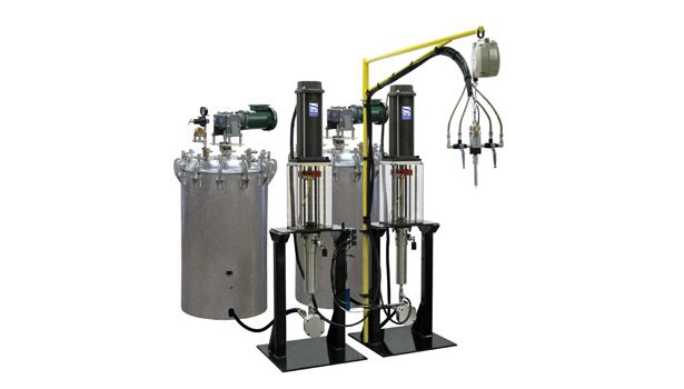
Metering Technology
The ideal lab dispensing equipment to formulate two-part materials is a meter/mix dispensing system with a variety of available variables that can provide a wide range of tests without changing the mechanical portions of the two-part dispensing system. The need for ideal lab equipment is to develop a multi-use two-part meter/mix dispensing system for testing new material formulations, demonstrating new materials applications in material labs and applying new materials for production in customer facilities. This innovative concept keeps the metering system intact and changes the dispensing requirements without mechanical adjustment. Less equipment is also needed by the formulator.
In the past, a system’s metering cylinders or pumps were modified to change the ratio and flow rate while keeping the drive motor intact. This caused multiple metering cylinders, pumps and parts to convert meter ratios. With this innovation, the inverse has occurred. The metering cylinders or pumps are kept constant while the drive motor becomes the variable to change the ratio and the flow rate. This is the same concept as performed for one-part materials. For two-part materials, the innovative system has two independent drive metering units where the ratio and flow rate are determined electronically. The control panel can be set up with hundreds of different dispense programs that include different ratios and flow rates. Also, the programs can be set up to vary the flow rate during dispense with each ratio.
This new two-part dispensing equipment includes independent servo-drive motors that provide the highest level of precision dispensing for new formulated materials. For maximum control and monitoring of ratio and flow rate, the metering cylinders used for this technology are positive rod displacement meters that provide the lowest impact and shear on material formulations, along with maximum fluid volume and ratio control, which does not allow bypass of materials.
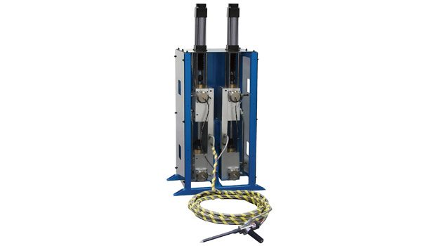
Dual-Drive Technology
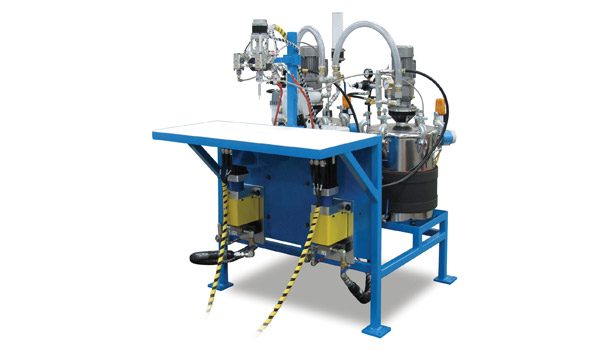
The ideal two-part dispensing system for material formulation includes dual servo-electric drive sources, independent pressure monitoring and intelligent
The ideal two-part dispensing system for material formulation includes dual servo-electric drive sources, independent pressure monitoring and intelligent controls. |
controls. With this system, each material is controlled independently and meaningful process data can be obtained. The goal behind this design is to control and monitor the entire dispense process, allowing the process to be defined, measured, and verified. With established known inputs, a variable can be introduced, evaluated and its process impact understood.
The dual servo-motors drive two independent rods into the metering chambers, displacing their respective volumes (known as Archimedes’ Principle). Displaced materials exit the metering cylinders through the on/off valve and static or dynamic mixer. The displaced volume is controlled by the distance the motor pushes the rod into the chamber, and the rate at which it is moved equates to the flow rate. Two-component fluids can be of different viscosities and densities, and all fluids are compressible at different rates. When acted upon, compression needs to be considered since the fluids will potentially move at different rates when metering forces are applied, resulting in the movement of one fluid before the other. To minimize this phenomena, the metering system must be designed with as little fluid as possible being acted upon by the metering rods. With the use of independent drive sources, each material can be acted upon separately to achieve the desired results of simultaneous fluid movement. When dispensing begins, each material will resist flowing and generate measurable pressure as it exits the system. These pressures are monitored by the pressure transducers in the fluid circuit. It is expected that each fluid will generate a different pressure, and this pressure requirement will command the force developed by the drive motors.
From a quality control standpoint, materials can be dispensed on ratio, producing physical examples of what is correct. Samples can also be produced with variances in the ratio to understand what changes in the physical properties of the end product occur when the chemistry of the adhesive is altered. This ability allows the manufacturer to establish quantifiable parameters for production norms. Another advantage of the variable-ratio feature is that a host of materials can be quickly evaluated, affording the manufacturer the option to change formulations without physical changes to the dispensing system. With independent drives, the real-time ratio can be monitored and assured each time an assembly is being produced.
Monitoring and Control
Independent pressure monitoring and control are key components in a quality dispense system. Materials are fed to the metering system from the supply source either by the force of gravity or an ancillary device such as a pressure tank or pump. Each of these conditions generates the measurable force or pressure that is necessary for movement of the fluids. Movement of fluid is required to recharge the metering system, and its pressure must be known.
For example, if we assume that a cylinder requires 5 cc of material and the pressure generated during the dispense cycle is 25 psi, it is ideal to reload the cylinder to 25 psi. If the reload pressure is 15 psi, the fluid will delay movement out of the cylinder until it reaches 25 psi, enough force to overcome the resistance to flow under dispense conditions. This can result in one material exiting the system before the other, resulting in an off-ratio condition and a wet spot in the mix due to lack of enough material in one cylinder at enough pressure to overcome compression compared to the movement of the other fluid.
Conversely, over-charging a cylinder will result in the same off-ratio/wet spot condition. This occurs when excess force is applied to a fluid in a contained area, and the contained area is opened during the dispense cycle. Over-pressurized material will leave the cylinder as a natural reaction to equalize pressure with atmospheric pressure, and this movement is equal to the excess pressure present. Simply put, 10 cc of material can be put into an area designed to hold 5 cc if enough pressure is applied. The resulting surge becomes part of the metering without the benefit of a controlled mechanical movement.
It is important to match the reload pressure to the dispense pressure. Pressure transducers provide a means of understanding the forces present. When electronically tied into precise motion control, systems can then be stabilized to optimum performance parameters. The pressure monitors also act as a check that the supply sources are functioning correctly. If the supply system were to run out of material or the transfer equipment malfunction, the pressure transducers would detect a low pressure condition during the reload cycle and inhibit the system from dispensing.
Pressure monitoring is also useful in the detection of gelling in the static mixer. If the material begins to gel in the mixer, the viscosity of the material in the mixer will increase, causing increased pressure in the metering system during the dispense cycle. If the material reaches the high limit of the preset high pressure setting, a fault will occur and inhibit the dispense cycle.
Coupling Monitoring with Dual Drives
Total control of the metering process is achieved when dual electric drives are combined with independent-pressure transducers. When the system calls for material from the supply source, the incoming pressure is irrelevant. Due to differences in material viscosities, vastly different pressures may be required to move the material from its supply source to the metering system. This viscosity can be affected by temperature, as well as differences in lot numbers from the material supplier.
Assuming the optimum dispense pressure is 25 psi, the A side material supply is 5 psi and the B side material supply is 250 psi, the pressure transducers will read this incoming data and send commands to the independent servo motors to compensate. The A side motor will advance the metering rod into the chamber, adding pressure until it reaches the desired 25 psi, while the B side motor will withdraw the metering rod from the chamber, thus depressurizing the fluid until it is reduced to 25 psi. At that time, the system will be give the OK to the dispense command.
The system can also run a diagnostic function to ensure integrity of the fluid control valves and rod seals by inducing a high pressure condition and holding this condition for a set period of time. If a pressure loss is noted during the hold time, it would indicate maintenance is required to a component.
Through the controls architecture, meaningful data can be collected about the dispense process in real time. Ideal for use by a quality control department, this feature includes A and B material volume dispensed, dispensed vs. requested volume, volume per cycle, volume trend charting, A and B material ratio, ratio trend charting, last ratio and flow rate dispensed, A and B material pressure trend charting, and drive motor monitoring.
For more information, call (734) 459-8600, email sales@sealantequipment.com, or visit www.sealantequipment.com. References for this article were provided by Carl E. Schultz, formerly of Sealant Equipment & Engineering, Inc.

