Ultrasonic Systems Inc. (USI) teamed up with a major EMS company to evaluate USI's Performa fluxing system for lead-free wave soldering. The primary objective was to establish the required flux deposition to achieve the desired soldering results for a given customer process. This objective is verified when complete topside solder flow and low post-soldering flux residue is achieved. The adjustable parameters for the Performa spray fluxer used to set flux deposition include flux flow rate to the spray head, traversing speed of the spray head, and the pitch of the traversing spray head. The amount of flux deposited to achieve the desired soldering results differs based on the board to be soldered and the flux brand used.
FLUXING PROCESS DEVELOPMENT
No-Clean ProcessIn the ideal no-clean soldering process, the flux applied to the board is consumed in the soldering process, virtually eliminating post-soldering flux residue. If too much flux is applied, excess post-soldering flux residue will be the result. Thus, it is crucial to apply only the amount of flux required to facilitate soldering. To do this properly, a spray fluxing system must apply the flux uniformly to the bottom surface of the circuit board and into the through holes. In order to maintain this process throughout a production shift, the spray-fluxing system must have the capability of repeating the preset flux deposition amount with very little variation.
Optimal Flux Deposition Amount
The flux manufacturer provides guidelines for the typical flux deposition range for the chosen flux. The flux deposition is specified in micrograms of flux solids per square inch. A typical deposition range might be 750-1,500 µg/in2 of flux solids on the circuit board. The best no-clean process is to use the lowest possible amount of flux solids and still achieve acceptable soldering results.
The following procedure can be used to set up the spray fluxing system for the optimal flux deposition of a specific flux and circuit board to be soldered:
1. Set the spray fluxer traversing speed and flux flow rate to deposit the flux at the high end of the specified deposition range.
2. Ensure that the wave-soldering machine preheats and conveyor speed are set within the flux manufacturer's recommended guidelines.
3. Run a test board through the fluxer and wave-soldering machine.
4. Inspect the soldered board for complete bottom-side soldering and topside fillets.
5. If the soldering results are acceptable, reduce the flux deposition setting on the spray fluxer by 10% and run another test board.
6. Continue reducing the flux deposition setting in 10% increments and running test boards until the topside fillets begin to deteriorate. This is the point just below the optimal flux deposition setting for a no-clean process.
7. The lowest flux deposition setting that achieves complete bottom-side soldering and excellent topside fillets is the optimal deposition setting for the spray-fluxing system.
Fluxing Process Characterization
Three experiments were developed and conducted to measure the performance of the fluxing system. These trials were also used to create an operating process matrix to assist in future setups. The parameters measured were:
1. Flux flow rates to the fluxer spray head
2. Flux weight deposited per circuit board
3. Flux deposition uniformity and through-hole penetration
Tools
1. Wave-soldering machine
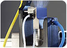
2. Performa fluxing system
3. Low-solids, no-clean, VOC-free flux
4. Bare .063" PCB with .035" holes at .125" centers
5. Litmus paper
6. Digital scale
7. 250-ml beaker
8. 50-ml beaker
9. Bare PCB
TEST #1: FLUX FLOW RATES
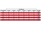
Objective: The Performa fluxing system delivers flux to the spray head via a positive-displacement gear pump and ON/OFF solenoid valve. The basis for this test was to measure the volume of flux flow to the fluxer spray head based on a percentage of pump speed (30-100%), and to measure for repeatability. Low-solids, n-clean, VOC-free flux was used for this test.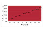
Conclusion: Flux flow rate to the spray head increases lineally relative to pump speed, and is highly repeatable.
TEST #2: FLUX WEIGHT PER CIRCUIT BOARD
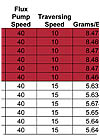
Objective: The amount of flux the Performa fluxing system deposits on a circuit board is the sum of two variables: 1.) flux flow rate to the spray head; and 2.) traversing speed of the spray head.If either the flux flow rate or the spray head traversing speed are changed, the total flux weight applied to a circuit board will change. The basis for this test was to measure how the combination traversing speed and flux flow rate affects the amount of flux applied to a circuit board, and to prove good repeatability.
Test: Experiments were conducted with the following inputs: 1.) 40% flux pump speed at a traversing speed of 10 inches per second; and 2.) 40% flux pump speed at a traversing speed of 15 inches per second.
The Performa system was programmed to target a spray area of 63 in2. When the system was activated, flux flow was diverted to a graduated beaker for measurement.
Conclusion: As shown in Table 2, the traversing speed directly affects the amount of flux applied to the circuit board. The precise control over traversing speed and flux flow rate provides a flux deposition variation of about ± 1%, or 98% deposition repeatability.
Calculating Flux Deposition - Microgram per Square Inch (g/in2)
To calculate the deposition of flux on a circuit board, in a pallet, with an exposed area of 9" wide and 12" long.Following are the inputs to consider:
- Traversing speed of spray head 12 inches per second (ips)
- Flux pump speed 35%
- Percentage of flux solids 4%
- Base carrier of flux water
1 cc of VOC-free (water-based) flux weighs about 1 g (1 cc of alcohol based flux weighs about 0.8 g). 1 g = 1,000,000 micrograms.
The weight of flux applied to the target spray area is 6.56 g, which is 6,560,000 micrograms. The flux solids content is 4% of this value, or 262,400 micrograms of flux solids. The flux deposition is the total flux solids divided by the sprayed area (120 in2), providing a total of 2,187 µg/ in2.
The transfer efficiency of the ultrasonic spray head is better than 90%. Thus, assuming 10% of the flux sprayed onto the circuit board is wasted, the calculated deposition is reduced by 10%, giving a total deposition of 1,968 µg/ in2.
With this information, incremental changes can be made to pump speed and/or traversing speed to change overall flux deposition.
TEST #3: FLUX DEPOSITION UNIFORMITY AND THROUGH-HOLE PENETRATION
Objective: The basis of this test was to measure flux uniformity and through-hole penetration by spraying flux through a test PCB onto litmus paper. The pattern produced on the litmus indicates flux through-hole penetration and uniformity. The Performa fluxing system produces a flat, rectilinear spray pattern, and passes under each through-hole location twice.Test: Four trial runs were conducted using the following parameters:
1. Traversing head pitch of 2.5 inches per spray stroke
2. Traversing head pitch of 3.5 inches per spray stroke
3. Flux pump speed of 30%
4. Flux pump speed of 40%
Conclusion: The resulting pattern on the litmus paper indicates that flux has penetrated every through-hole and that the flux applied is uniform. Spray pattern consistency and flux penetration are repeatable on boards 2-24 inches wide.
SUMMARY
This testing conducted at the customer's facility in Europe concluded that the Performa spray-fluxing system is capable of achieving a true no-clean process in a lead-free environment. The data also confirms that the fluxer delivers a uniform and repeatable process.The results of the experiments conducted measuring the performance of the fluxing system are summarized as follows.
1. Flux flow rates were measured to be both linear and repeatable.
2. Flux deposition was repeatable to within ± 1%
3. Deposition uniformity and through-hole penetration were excellent based upon litmus paper test results.
This lead-free soldering process is currently in full production.
For more information, contact Stanley Soderstrom, Ultrasonic Systems Inc., 135 Ward Hill Ave., Haverhill, MA 01835; phone (978) 521-0095, ext. 39; or e-mail sjsoderstrom@ultraspray.com .
Ultra-Spray® is a registered trademark of Ultrasonic Systems Inc.
HOW IT WORKS: ULTRASPRAY® TECHNOLOGY
UltraSpray, a nozzle-less spray head technology, produces an ultra-uniform, rectangular spray pattern that is ideal for precision spray coating in the electronics industries.The spray head is comprised of three components: an ultrasonic transducer, a voltage-mode ultrasonic power generator, and an independent fluid applicator.
Ultrasonic transducers operate at fixed frequencies - 45 kHz, for example - and produce vibrations with maximum amplitude at their tip. They consist of converters and horns, each designed to operate at the same frequency. Converters use disc-shaped piezoelectric elements that are sandwiched between a cylindrical titanium front section and a steel back section, to convert high-frequency electrical energy into high-frequency mechanical energy. Horns are stepped blocks of titanium designed to focus mechanical energy, produced by the converter, at the transducer tip.
Ultrasonic generators produce the power demanded by the transducers, thus supplying a constant sinusoidal voltage at the operating frequency of the converter. They track these power demands by adjusting the operating frequencies and power factors created by "temperature" and "load" changes. Load changes occur when more or less liquid is sprayed from the atomizing tip. A microprocessor monitors these dynamic conditions and automatically adjusts the operating frequency for optimum transducer performance. If an overload condition occurs, the power generator is turned off and indicates a fault condition on its display.
Fluid applicators deliver liquid to the atomizing tip of the transducer and direct airflow to shape and add momentum to the ultrasonically produced spray. Liquid and airflow are independent.
Fluid applicators supply liquid to the atomizing tip in a "slot flow" form to match the width of the transducer horn. As liquid flows onto the horn, it is disintegrated into small drops and propelled into the air by the ultrasonic energy. The resulting spray pattern is a uniform "sheet" of spray equal to the width of the horn. The air directors expand and shape the ultrasonically produced spray into a rectangular pattern, and give the liquid drops enough force to overcome ambient air currents and penetrate the through-holes and vias of the PCB.