
In order to achieve a successful solution to a dispensing challenge, one must consider the following:
- Type of material,
- Material supply or feed system,
- Metering unit,
- Dispense valve and
- Type of automation.
In general, the best teacher is experience because there are a wide variety of parameters that need to be considered. Good communication between the material supplier, equipment supplier, integrator and the customer, who has the best knowledge of the application, is paramount.
Materials
There are many types of materials or chemistries. The selection of these materials is very important to the integrity of the adhesive bond to the substrate and to ensuring that your product does what you want it to do when it is assembled. The material supplier is the best person to be contacted for information on the applicability of certain chemistries and adhesive systems for the application. Some benefits of different materials include:- Epoxies are easy to custom formulate and accept fillers readily; plus, they result in excellent high-shear properties.
- Polyurethanes have a high flexibility and respond well in applications with thermal shock and a corrosive environment.
- Acrylics and methacrylates bond dissimilar substrates very well.
- Silicones are excellent for sealing applications.
- Viscosity, which is a measure of the liquid's resistance to flow, is a key property. Another consideration is the thixotropic nature of the material. For example, does its viscosity become lower with shear stresses imparted by agitation? Particulars of the feed system and the metering system will change with different viscosities. Different viscosities of materials can be ball-parked with common, everyday materials at room temperature. For example, water has a viscosity of 1 centipoise (cps) at room temperature, followed by maple syrup at 5,000 cps, followed by ketchup at 50,000 cps, peanut butter at 250,000 cps and shortening at 1,200,000 cps.
- Specific Gravity is the density of a material compared to water. Typically the specific gravities of the different components in a two- or multiple-component system are available.
- Mix Ratio can be stated as a weight or volume ratio. Do not assume one or the other if not stated specifically. Use the following formula if required to convert.
- Moisture Sensitivity represents the hygroscopic nature of materials. With polyurethanes and other materials that are moisture sensitive, a nitrogen or dry-air blanket and use of lubricating seals on pump shafts to isolate the materials from moisture are recommended.
- Pot Life represents the working life of the material. Reactive chemistries assume a pot life. The reactive components must be kept separate with the use of motionless mixers. Otherwise, solvent purging is needed. With environmental concerns high, disposal of solvents is an issue.
- Safety and Handling includes the corrosive and hazardous nature of materials. In some cases, an equipment supplier will ask for the Material Safety Data Sheets as well as the technical data sheets for the material.
Effect of Materials on Equipment Design
Let's consider the effect of the material component parameters on the equipment design. With a high-viscosity material, heat may be required to lower the material viscosity to make it easier to process. Additionally, larger pumps with a higher power factor or a feed system with ram and follower plate will be required. If bubbles exist in the material, consider heating or degassing with a vacuum tank. Abrasive fillers in the material always require special consideration. Heat with agitation, recirculation, and anti-abrasion materials of construction are all important considerations.One must also consider how the mixed material properties impact machine options. Pot life of the material may dictate the use of automatic flushing, cooling of the head to slow down the reaction time or the use of an anti-gel timer. If your application requires the material not to drip, consider a snuffer valve or a positive-displacement pinch valve. For better shot control, consider a linear encoder, stepper or a servo-drive but remember that, typically, the more accurate or repeatable the higher the cost of the system. If you require automation, there are a myriad of different options, degrees of sophistication and price levels.
The charts given here outline some of the options to consider, depending on the individual component parameters and the mixed material properties.
Material Supply Techniques
Materials come in various forms and must be fed out of their supply containers to be metered, mixed and dispensed. Materials can be supplied in bulk with 5-gallon pails or 55-gallon drums, large totes or tanks, or in small feed containers that include cartridges, syringes or 1-gallon cans. Depending mainly on the viscosity of the material, the feed system is gravity or pressure fed.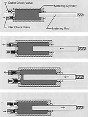
Metering Techniques
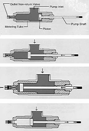
As you contemplate metering equipment, there are many considerations: the size of the part, the production rates, the manufacturing environment, continuous dispensing, single or multiple shots, fixed- or variable-ratio machines, etc. There are also many different metering techniques with varying degrees of accuracy, precision and reliability.The first metering technique we will review is the positive-displacement piston pump (Fig. 1). Materials can be pressure or gravity fed to the pump inlet. The pump shaft is moved forward, pushing the piston into the beveled metering tube. As the piston advances, the material in the metering tube is displaced through the outlet non-return check valve.
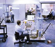
The advantages of this technique include a wide intake with no inlet check valve, 0.5% metering accuracy, handling of materials that range from water-thin to paste viscosity with filler, use of low-pressure seals, accuracy not impacted by viscosity changes and the ability to phase the individual components. Phasing is an important characteristic with this technique. It is the ability to adjust the pump shaft so that the materials enter the motionless mixer at the same time, avoiding a lead-lag situation at the material outlet of the mixer. Equipment with piston pumps is shown in Figure 2.
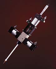
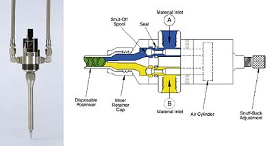
The second metering technique is similar to the first but, instead of a piston, a metering rod and inlet seal are used. Rod positive-displacement metering can take various forms as larger units or in compact, lightweight designs for small-shot dispensing of materials in the 0.005- to 5.0-cc range (Fig. 3). These units can handle ratios of materials from 1:1 to 25:1 with cycle rates from 1 to 60 cycles per minute. The use of pneumatically actuated spool assemblies keeps the A and B materials separate in the valve and divorces the material inlets from the outlets to the mixer. As spools shift to the right, the material-feed inlets are opened, materials are forced into the metering chamber by a pressurized feed system, outlet ports are blocked and the metering rod is retracted to a precisely set position determining the volume of each material. Next the balanced spool assemblies shift to the dispense position, allowing the material path to the mixer inlet to be open while the material-feed inlet ports become blocked and the metering rod remains in the retracted position. Lastly, the metering rods push down and force the individual components into the disposable mixer with each component dispensed at the predetermined ratio.
The next metering technique involves an inlet and outlet check valve (Fig. 4). This conventional rod displacement pump allows material to enter through an inlet check valve and when the metering rod advances, material exits through an outlet check valve.
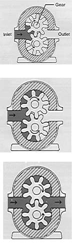
Gear pumps have been used for years and are also very popular. The gear pump (Fig. 5) draws the material into the inlet of the pump to be metered by teeth around the inside circumference of the pump. The teeth pull the material through the pump and dispense it through the pump outlet. The use of gear pumps is limited to lower viscosities, very close mix ratios and non-abrasive mixed materials. They are popular for continuous-bead applications with adhesives and single-component greases. These pumps are not preferred for small-shot applications.
The peristaltic pump is another metering technique that utilizes plastic tubing of various sizes that is squeezed shut by rollers pushing the material from inlet to outlet. Peristaltic pumps are used for small shot sizes when changing materials frequently. These pumps are not very accurate because of slippage, stretching of the plastic tube and roller wear.
Dispense Valves
If you are dealing with a multiple-component material, you must thoroughly mix before dispensing. Mixing properly is critical to realizing the intended properties of the material. Several options exist in valves and mixing techniques:- Dispense valves with motionless mixers;
- Dynamic mixers, with or without solvent flushing;
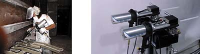
- Impingement mixing, which uses a high-pressure, self-cleaning mix head; and
- Mixer used with a pinch valve to control the shot after mixing.
Automatic Dispense Valve
The over/under injection block is used for wide-ratio materials. The low volume is introduced into the center of the high-volume stream prior to entering the motionless mixer. Solvent and air purging are used to flush the injection block and mixer.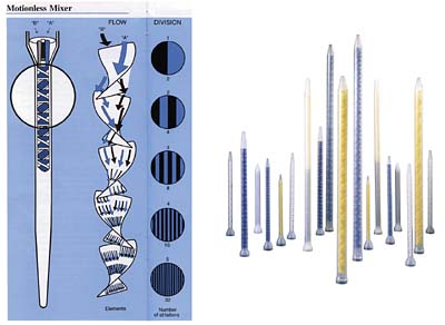
Motionless Mixer
The most common motionless mixers use a series of right- and left-handed helical elements at 90 degrees with no moving parts (Fig. 7). Materials are divided, recombined and re-divided. Mixers are available in a wide variety of sizes. They can be made of plastic for low cost and disposability so they do not require solvent purging or metal construction that can be solvent flushed.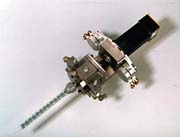
Dynamic Mixer
Dynamic mixers use high shear to mix the different components. Pin/blade and helical designs are common; however, they require solvent purging. To address this, plastic mixers with rotating mix elements have started to become very popular (Fig. 8). They rotate at speeds up to 5,000 rpm and do not require solvent purging.Snuffer Valve
The snuffer valve has the material flow commencing on the forward stroke of the valve spool. When the spool retracts, a vacuum is created and an adjustable, drip-less snuff-back occurs at the dispense-nozzle outlet.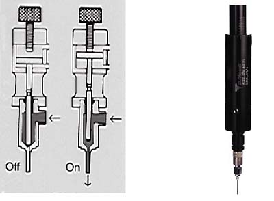
Needle Valve
The needle on/off valve allows the material flow to commence when the needle retracts from its seat and stops when the needle reseats (Fig. 9).Pinch Valve
The pinch valve allows the material to flow when the flexible dispense tubing shutoff is released and stops when the tube is pinched closed.Application Technique
In addition to the type of mixer, one must decide the application technique.- Manual refillable metering and dispense gun;
- Manual application with a hand-held or fix-mounted dispense valve;
- Robot application with a Cartesian or articulated-arm robot.
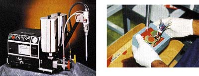
Manual-Refillable Dispense Gun
This product (Fig. 10) is new on the market and uses a refillable metering and dispense gun to enable two-part-adhesive users a cost-effective way to use bulk-packaged materials. This technology allows end users to realize significant savings over convenience cartridges.
The system uses an air piston to dispense material from two refillable metering tubes. When empty, the gun is placed in a docking station to refill the metering tubes. Once the gun is filled, the user carries it to the part where the adhesive will be applied. These guns are offered in standard ratios from 1:1 to 10:1 and use disposable motionless mixers.
Manual Application With a Hand-Held or Fixed-Mounted Valve
Most users fix-mount the valve or add a handle to manually apply the material to the part (Fig. 11). As production requirements increase, these same customers consider automating the process.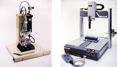
Automation of the Dispensing Operation
With increased volumes of parts and higher quality standards combined with pressure to reduce costs, it has been imperative that production engineers take a good look at automating the process of dispensing materials onto a part.One of the most basic devices used is a "Z" lift (Fig. 12). It is typically used with rotary tables or indexing conveyors. It is typically pneumatically operated and designed to move the dispense valve vertically to a preset height. Once the valve is elevated, a new part is indexed under the valve nozzle, the valve is lowered and dispensing starts. After completion of the dispense cycle, the valve is lifted vertically and a new part is indexed into position.
An XYZ table can handle applications requiring several different dispense patterns. The three-axis proportioners provide the ability to combine lines, arcs, dots and circular paths. Most of the systems have sophisticated programming capabilities that can accommodate many different part configurations. Factors that determine the size and cost of a table are the work envelope, payload weight, speed, accuracy, programming capabilities and ease of programming.
The most sophisticated motion device is a multi-axis robot. It ranges from a bench-top unit to a freestanding unit.
The standard drive for dispensing equipment has been pneumatic-air cylinders, but these do not provide good beads when coupled with motion because minor changes in flow rates are visible when not compensated for. When greater control is required, a stepper or a servo drive is used that is adapted to a linear actuator to convert the rotary motion of the motor to a linear motion.
Stepper motors are a cost-effective means of providing precise digital control to the application. The motors do not require a feedback device to operate. They are unsuitable for high-speed dispensing because they will lose torque as their rotational speed increases.
Servomotors offer the same digital control with the advantages of a closed-loop system. Servomotors are suitable for high-speed dispensing, as well. A computer or programmable logic controller provides controls for both the stepper and servomotors. Patterns can be programmed, stored and recalled to decrease set-up times.
Automation offers many benefits from increased production rates, accuracy and consistency to decreased labor costs. Automation is becoming the standard for material-dispensing applications.
Last Word
Selecting the proper meter, mix and dispense solution is not an easy task and in many instances will depend on experience with different materials and different technologies in various applications. The task is made a great deal easier when the proper material and process information is gathered upfront. This coupled with experience in the application will minimize any risks.Additional information on meter/mix dispense machines for bonding, sealing, gasketing, doming, dispensing automation and cartridge filling is available from Liquid Control Corp., 8400 Port Jackson Ave., N.W., N. Canton, OH 44720; phone 330-494-1313; fax 330-494-5383; e-mail salesinfo@liquidcontrol.com or visit the Web site www.liquidcontrol.com. Or Circle No. 73.
