Spray Solutions
Simulation
helps develop spray gun with 50% larger pattern in less time.

Graco plural-component spray guns are designed to apply products that need to be mixed just prior to spraying, such as polyurethane foam insulation. The performance of these guns depends upon thoroughly mixing the two polyurethane foam components - the resin and the catalyst. It’s also important to control the motion of the spray as it leaves the gun in order to provide the desired pattern shape on the surface to which it is applied.
Previously, the company used a long and expensive trial-and-error process that provided acceptable - but not optimal - designs. Recently, Graco began using computational fluid dynamics (CFD) to simulate the flow of resin and catalyst inside the gun.
Polyurethane foam insulation has become increasingly popular because it does a better job at preventing air infiltration than traditional fiberglass insulation. Graco’s plural-component spray guns are designed with the mix chamber inside the body of the gun. When the gun is triggered, the two fluids blend inside the gun’s mix chamber and the mixed material is propelled through the chamber or spray tip, atomizing the fluid.
These guns are suited for fast-set fluids, such as polyurethane foam with set times typically under six seconds. With these types of materials, the resin and catalyst must mix completely to achieve the full foam rise desired. Most guns designed for polyurethane foam feature a round pattern mix chamber that does not require a tip. The swirling pattern generated in the mix chamber results in the material being applied in a conical pattern on the substrate. In addition, this type of mix chamber stays cleaner longer because there are no small spray orifices that can clog.
In the past, the company’s engineers would have started with a benchmark design, probably based on a scaled-up version of the original design. They would have built and tested the new design identifying performance problems such as incomplete mixing that cause an undesirable foam quality. They then would have guessed at the reason for the problem, changed the design, built a new prototype and run tests. The process would have continued, often through scores of prototypes, until a satisfactory design had been created. Anderson said it would have taken 9-12 months to generate an acceptable (though far from optimized) design of all the various sizes in the days before the company began using CFD. Optimizing the design was not usually practical because of the inability to predict flow patterns and the time and cost required for each design iteration.
FloEFD substantially reduces the amount of skill and time required to simulate fluid flow through its use of native 3-D CAD data, automatic gridding of the flow space, and managing of flow parameters as object-based features. The skills required to operate the CFD software include a simple knowledge of the CAD system and the physics of the product, both of which the company’s design engineers already have. The engineers are thus able to focus their time and attention on optimizing the performance of the product as opposed to operating the software.
Anderson constructed a benchmark design using the company’s Pro/ENGINEER Wildfire CAD system and then used FloEFD to directly analyze its flow performance. The cylindrical mixing chamber featured two inlet ports perpendicular to the centerline of the mixing chamber for the two components in the polyurethane system. Anderson offset the ports in opposite directions above and below the centerline to provide the swirl needed to provide a round pattern on the wall. He applied the boundary conditions directly to the Pro/ENGINEER model, including various levels of inlet fluid pressure provided by a pump and atmospheric pressure at the outlet of the nozzle. The CFD software then automatically meshed the open area inside the nozzle and generated flow velocity and pressure results throughout the internal passages of the gun.

“During this process, I was able to achieve the required level of mixing and round shape while substantially increasing the size of the spray pattern,” Anderson said. “The complete design process of all sizes took only about 3-4 months, or about a third of the time the trial-and-error method required. The use of software prototypes made it possible to explore a much wider design space than would have been possible with physical prototypes. As a result, we are confident that this design is the best that can be achieved within the constraints of the project.”
 “It’s important to note that I achieved these results
despite the fact that I am a design engineer without any training in CFD,” he
added.
“It’s important to note that I achieved these results
despite the fact that I am a design engineer without any training in CFD,” he
added.
This gun enables operators to spray foam over a larger area and get a smoother finish. The operator can also get better pattern overlap with a more even foam buildup with this design. This project is only one of a large number of similar successes using CAD-embedded CFD software at Graco. For example, the company has used CFD to optimize the design of many different models of Fusion spray guns designed to handle different materials, different pressures, and different spray pattern shapes. Graco has expanded its use of FloEFD software to the point that the company now uses FloEFD at three different divisions. In each division, the software is used sequentially by a number of different design engineers rather than being limited to a fluid dynamics expert as was required with the previous tool. Anderson said that the use of CFD has made it possible for Graco to substantially improve the performance of its products while reducing time to market.
For more information about FloEFD, visit www.mentor.com/mechanical or contact Mentor Graphics Corp., Mechanical Analysis Division, U.S. Headquarters, 300 Nickerson Road, Suite 200, Marlborough, MA 01752; phone (508) 480-0881; fax (508) 480-0882; e-mail info-mechanical@mentor.com; or visit www.mentor.com/mechanical.
In the U.K., contact Mentor Graphics Corp., Mechanical Analysis Division, Division Headquarters, 81 Bridge Road, Hampton Court, Surrey KT8 9HH, England; phone +44 (0) 20 8487 3000; e-mail info-mechanical@mentor.com; or visit www.mentor.com/mechanical.
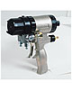
Figure 1. Graco Fusion Air Purge Spray Gun
Graco plural-component spray guns are designed to apply products that need to be mixed just prior to spraying, such as polyurethane foam insulation. The performance of these guns depends upon thoroughly mixing the two polyurethane foam components - the resin and the catalyst. It’s also important to control the motion of the spray as it leaves the gun in order to provide the desired pattern shape on the surface to which it is applied.
Previously, the company used a long and expensive trial-and-error process that provided acceptable - but not optimal - designs. Recently, Graco began using computational fluid dynamics (CFD) to simulate the flow of resin and catalyst inside the gun.
Figure 2. Graco Fusion Mechanical Purge Spray Gun
Improved Performance
Visualizing the flow inside the gun leads to rapid design improvements. Simulation also enables Graco design engineers to evaluate the performance of software prototypes using less time and money. As a result, the company has improved the performance of its spray guns to industry-leading levels. For example, Graco used CFD to develop one model of its Graco Fusion plural-component spray gun that provides a 50% larger spray pattern than traditional guns, substantially improving productivity for the contractors applying the foam insulation.Polyurethane foam insulation has become increasingly popular because it does a better job at preventing air infiltration than traditional fiberglass insulation. Graco’s plural-component spray guns are designed with the mix chamber inside the body of the gun. When the gun is triggered, the two fluids blend inside the gun’s mix chamber and the mixed material is propelled through the chamber or spray tip, atomizing the fluid.
These guns are suited for fast-set fluids, such as polyurethane foam with set times typically under six seconds. With these types of materials, the resin and catalyst must mix completely to achieve the full foam rise desired. Most guns designed for polyurethane foam feature a round pattern mix chamber that does not require a tip. The swirling pattern generated in the mix chamber results in the material being applied in a conical pattern on the substrate. In addition, this type of mix chamber stays cleaner longer because there are no small spray orifices that can clog.
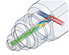
Figure 3. Flow Trajectories in the Mix Chamber of a Fusion AP Spray Gun
Designing a New Spray Gun
Graco Senior Project Engineer Rick Anderson was assigned the task of developing a new spray gun with a wide pattern mix chamber capable of delivering round spray patterns with a diameter 50% greater than standard guns. Simply scaling up the mix chamber from existing designs would have been inadequate because fluid flow usually changes substantially when the scale of a design changes. The difficult part of the design process was achieving the high level of mixing needed to achieve proper foam rise with the typical polyurethane material and providing the helical flow pattern needed to provide a round pattern shape as the material hits the wall.In the past, the company’s engineers would have started with a benchmark design, probably based on a scaled-up version of the original design. They would have built and tested the new design identifying performance problems such as incomplete mixing that cause an undesirable foam quality. They then would have guessed at the reason for the problem, changed the design, built a new prototype and run tests. The process would have continued, often through scores of prototypes, until a satisfactory design had been created. Anderson said it would have taken 9-12 months to generate an acceptable (though far from optimized) design of all the various sizes in the days before the company began using CFD. Optimizing the design was not usually practical because of the inability to predict flow patterns and the time and cost required for each design iteration.
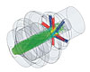
Figure 4. Flow Trajectories in the Mix Module of a Fusion MP Spray Gun
Switching to CAD-Embedded CFD
A few years ago, Graco purchased CFD software and trained one of its engineers to use it. The software made it possible to visualize flow inside the spray guns and evaluate proposed designs in much less time than physical prototyping, and substantial performance improvements were achieved in several products. However, the software was expensive, difficult to use and required a considerable amount of time to analyze each design. What’s more, the only engineer trained to use the software eventually left the company. Engineers decided to evaluate alternative CFD software and found a product that is closely integrated into the computer-aided design (CAD) software used by the company’s design engineers: FloEFD from Mentor Graphics Corp.’s Mechanical Analysis Division (formerly Flomerics).FloEFD substantially reduces the amount of skill and time required to simulate fluid flow through its use of native 3-D CAD data, automatic gridding of the flow space, and managing of flow parameters as object-based features. The skills required to operate the CFD software include a simple knowledge of the CAD system and the physics of the product, both of which the company’s design engineers already have. The engineers are thus able to focus their time and attention on optimizing the performance of the product as opposed to operating the software.
Anderson constructed a benchmark design using the company’s Pro/ENGINEER Wildfire CAD system and then used FloEFD to directly analyze its flow performance. The cylindrical mixing chamber featured two inlet ports perpendicular to the centerline of the mixing chamber for the two components in the polyurethane system. Anderson offset the ports in opposite directions above and below the centerline to provide the swirl needed to provide a round pattern on the wall. He applied the boundary conditions directly to the Pro/ENGINEER model, including various levels of inlet fluid pressure provided by a pump and atmospheric pressure at the outlet of the nozzle. The CFD software then automatically meshed the open area inside the nozzle and generated flow velocity and pressure results throughout the internal passages of the gun.
Figure 5. Cutaway View of a Graco Fusion Air Purge Spray Gun
Iterating to an Optimized Design
As expected, the performance of the benchmark design was far below specifications. Anderson embarked upon an interactive process that involved parametrically changing key design variables such as the length, diameter and amount of offset of the impingement ports and the diameter of the exit hole. For each design iteration, he checked how thoroughly the two components mixed in the chamber and predicted the size and shape of the resulting output pattern from the analysis results.“During this process, I was able to achieve the required level of mixing and round shape while substantially increasing the size of the spray pattern,” Anderson said. “The complete design process of all sizes took only about 3-4 months, or about a third of the time the trial-and-error method required. The use of software prototypes made it possible to explore a much wider design space than would have been possible with physical prototypes. As a result, we are confident that this design is the best that can be achieved within the constraints of the project.”
Figure 6. Cutaway View of a Graco Fusion Mechanical Purge Spray Gun
This gun enables operators to spray foam over a larger area and get a smoother finish. The operator can also get better pattern overlap with a more even foam buildup with this design. This project is only one of a large number of similar successes using CAD-embedded CFD software at Graco. For example, the company has used CFD to optimize the design of many different models of Fusion spray guns designed to handle different materials, different pressures, and different spray pattern shapes. Graco has expanded its use of FloEFD software to the point that the company now uses FloEFD at three different divisions. In each division, the software is used sequentially by a number of different design engineers rather than being limited to a fluid dynamics expert as was required with the previous tool. Anderson said that the use of CFD has made it possible for Graco to substantially improve the performance of its products while reducing time to market.
For more information about FloEFD, visit www.mentor.com/mechanical or contact Mentor Graphics Corp., Mechanical Analysis Division, U.S. Headquarters, 300 Nickerson Road, Suite 200, Marlborough, MA 01752; phone (508) 480-0881; fax (508) 480-0882; e-mail info-mechanical@mentor.com; or visit www.mentor.com/mechanical.
In the U.K., contact Mentor Graphics Corp., Mechanical Analysis Division, Division Headquarters, 81 Bridge Road, Hampton Court, Surrey KT8 9HH, England; phone +44 (0) 20 8487 3000; e-mail info-mechanical@mentor.com; or visit www.mentor.com/mechanical.
Links
Looking for a reprint of this article?
From high-res PDFs to custom plaques, order your copy today!


