A Better Mix
Dual-axis centrifugal mixers can handle small batches of high-viscosity products quickly and efficiently.
 The axial flow paradigm has long been one of the most predominant mechanisms of mixing. This flow pattern is generally produced by a single-shaft mixer with axial flow impellers. It is characterized by flow down the center of the batch to the bottom of the tank, which is then deflected outward toward the wall by the container bottom. It then travels up the vessel wall and back across the surface, as shown in Figure 1.
The single-shaft mixer has limited use in the preparation of adhesives and sealants, as the axial flow patterns are difficult to reproduce in the high viscosities these products typically exhibit. When viscosity rises, mixing efficiency drops as distance from the mixing blade increases. Increasing the blade speed does little to compensate for loss of flow at the outer reaches of the tank. In addition, vortexes become deeper as speed increases, resulting in air entrainment.
To overcome these limitations, multiple shafts were introduced to provide both the shear and flow necessary to produce a uniform product. Multiple-shaft mixers are common in the production of adhesives and sealants. However, these multi-shaft mixers do not produce the same flow patterns. They also require additional clean-up, limit the ability to produce small batches, and do not always mix as efficiently in small sizes as larger production machines. In many cases, the only option available has been to manually assist the mixer or manually mix altogether.

The surface of water in a cup remains perpendicular to the force of gravity, acting on it regardless of the angle at which the cup might be held. The surface of material in the mixing container will remain perpendicular not to the force of gravity, but to the stronger centrifugal force created by the orbital speed of the container. The centrifugal force is a function of the distance from the center of rotation and the angular velocity. The dual-axis centrifugal mixer develops centrifugal acceleration in the range of 400 G.
Due to the angle at which the cup is held, the distance between the center machine axis and any point on the surface of the product continually changes as the cup rotates. Product flows to compensate for these changes, resulting in flow patterns from the edge of the container to the center of the batch.
As shown in Figure 3, this same flow pattern can be seen in the dual-axis centrifugal mixer. A center vortex forms and material travels down that vortex. The vortex, while present, remains shallow as the flow is created by centrifugal force acting on the product as a whole, instead of induced by a relatively small blade operating within the batch. The vortex is most evident in the T015 (time = 15 seconds) photo. Prior to the final photo, T135 (2 minutes, 15 seconds), surface eddies begin to form to further improve mixing as viscosity is reduced. Similar flow patterns can be seen in traditional liquid mixing when the mixing shaft is offset.
The dual-axis centrifugal mixer produces the axial flow patterns that are predominant in liquid mixing while overcoming the viscosity limitations of a traditional single-shaft mixer. Added benefits include reduced cleanup requirements, as all shafts are eliminated and the container remains the only contact part. Without shafts, it is possible to produce very small batches; standard units are capable of mixing batches as small as 50 grams and as large as 2,500 grams. (These batch limits can be extended with container adapters.)
In addition, the shallow vortex eliminates additional air entrainment during mixing. As vortex depth is not a limiting factor, the dual-axis centrifugal mixer can mix at high energy levels, which results in shorter batch times. In the adhesive and sealants industry, the mixer has been used for fast and efficient formulation qualification, pilot development, and small batch production.
For more information, contact the E.W. Kaufmann Co. at 140 Wharton Road, Bristol, PA 19007; phone (215) 364-0240; e-mail sschmidt@ewkco.com; or visit www.ewkaufmann.com.
Figure 1. Axial Flow in a Single-Shaft Mixer
The single-shaft mixer has limited use in the preparation of adhesives and sealants, as the axial flow patterns are difficult to reproduce in the high viscosities these products typically exhibit. When viscosity rises, mixing efficiency drops as distance from the mixing blade increases. Increasing the blade speed does little to compensate for loss of flow at the outer reaches of the tank. In addition, vortexes become deeper as speed increases, resulting in air entrainment.
To overcome these limitations, multiple shafts were introduced to provide both the shear and flow necessary to produce a uniform product. Multiple-shaft mixers are common in the production of adhesives and sealants. However, these multi-shaft mixers do not produce the same flow patterns. They also require additional clean-up, limit the ability to produce small batches, and do not always mix as efficiently in small sizes as larger production machines. In many cases, the only option available has been to manually assist the mixer or manually mix altogether.
Figure 2. Interior of a Dual-Axis Centrifugal Mixer
Dual-Axis Centrifugal Mixers
The dual-axis centrifugal mixer uses no shafts. Instead, it relies on two distinct rotational vectors and an angular alignment of the mixing container to produce its mixing ability (see Figure 2). First, a mixing container is held at a fixed distance from a center axis; the container orbits that axis at high speed. (If this were the only axis of rotation, the unit would effectively operate as a centrifuge, separating products based on density.) To complement this motion, the container rotates about its own center axis and the cup is angled toward the motor axis. This second axis of rotation and cup angle are essential to the generation of the mixing action.The surface of water in a cup remains perpendicular to the force of gravity, acting on it regardless of the angle at which the cup might be held. The surface of material in the mixing container will remain perpendicular not to the force of gravity, but to the stronger centrifugal force created by the orbital speed of the container. The centrifugal force is a function of the distance from the center of rotation and the angular velocity. The dual-axis centrifugal mixer develops centrifugal acceleration in the range of 400 G.
Due to the angle at which the cup is held, the distance between the center machine axis and any point on the surface of the product continually changes as the cup rotates. Product flows to compensate for these changes, resulting in flow patterns from the edge of the container to the center of the batch.
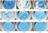
Figure 3. Surface Flow Pattern
Surface Flow
The mixing action of the dual-axis centrifugal mixer can be demonstrated with white and blue samples of children’s modeling compound. Approximately 80 grams of the blue and another 80 of the white were rolled into a ball, flattened into “hockey pucks” and placed into the mixing cup, with blue on the bottom and white on the top. The flow pattern observed in a traditional single-shaft mixer includes a vortex in or around the center of the mixing container.As shown in Figure 3, this same flow pattern can be seen in the dual-axis centrifugal mixer. A center vortex forms and material travels down that vortex. The vortex, while present, remains shallow as the flow is created by centrifugal force acting on the product as a whole, instead of induced by a relatively small blade operating within the batch. The vortex is most evident in the T015 (time = 15 seconds) photo. Prior to the final photo, T135 (2 minutes, 15 seconds), surface eddies begin to form to further improve mixing as viscosity is reduced. Similar flow patterns can be seen in traditional liquid mixing when the mixing shaft is offset.
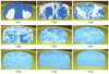
Figure 4. Internal Flow Pattern
Internal Flow
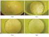
Figure 5. Powder, Paste and Liquid Mixing
Real-World Mixing
This type of mixer functions well in real-world operations, which often require the mixing of many dissimilar components. Figure 5 illustrates the mixing of a series of powders, pastes and liquids at a total mix time of 45 seconds. Typically, a 20-minute batch time is considered excellent for a traditional shaft-type mixer with much lower viscosities.The dual-axis centrifugal mixer produces the axial flow patterns that are predominant in liquid mixing while overcoming the viscosity limitations of a traditional single-shaft mixer. Added benefits include reduced cleanup requirements, as all shafts are eliminated and the container remains the only contact part. Without shafts, it is possible to produce very small batches; standard units are capable of mixing batches as small as 50 grams and as large as 2,500 grams. (These batch limits can be extended with container adapters.)
In addition, the shallow vortex eliminates additional air entrainment during mixing. As vortex depth is not a limiting factor, the dual-axis centrifugal mixer can mix at high energy levels, which results in shorter batch times. In the adhesive and sealants industry, the mixer has been used for fast and efficient formulation qualification, pilot development, and small batch production.
For more information, contact the E.W. Kaufmann Co. at 140 Wharton Road, Bristol, PA 19007; phone (215) 364-0240; e-mail sschmidt@ewkco.com; or visit www.ewkaufmann.com.
Links
Looking for a reprint of this article?
From high-res PDFs to custom plaques, order your copy today!


