Case Study
Adhesives at Work: Filters Reduce False Sealant Failures
Filtering can substantially reduce manual sealant inspection time, thus speeding up the automotive production line.
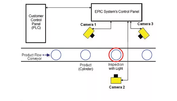

An automotive supplier uses a machine vision system to inspect up to 900 parts per min to substantially improve quality and productivity. The system checks for the presence and uniformity of a bead of sealant applied to the interior of a metal canister (see Figure 1).
During the application development, Chris Walker, project manager for EPIC Systems Inc., which provides turnkey solutions for advanced automation and machine vision systems, wanted to reduce the number of false failures—good parts that were mistakenly identified as bad by the machine vision system. In addition, Walker wanted to reduce the time required for inspection to accommodate planned future increases in line speed. He used a setup of polarizing filters and an ultraviolet (UV)/infrared (IR) filter to eliminate glare. The elimination of glare substantially reduced the number of false failures and also made it possible to reduce the number of digital image filters in the vision algorithm, reducing inspection time from 85 to 65 milliseconds.
Solving Inspection Challenge
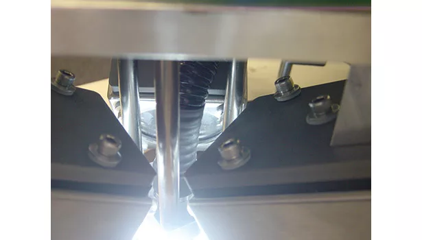
The application not only detects the presence of the sealant bead, but also determines its position and measures its width for consistency around the entire circumference of the 10-mm-wide by 10-mm-long canister. Three Cognex® In-Sight® vision systems were set up so that each captures a 120° segment of the interior surfaces of the canister. EPIC Systems developed the machine vision algorithm by using Cognex’s vision tools to inspect the interior surface.
The algorithm uses two different methods to simultaneously inspect the part, and only passes the part if both methods indicate the part is good. The first method uses edge tools to find the top edge and the bottom edge of the sealant and the top edge of the canister. Simple calculations then determine the width of the sealant bead and the distance of the bead from the top edge of the canister. The other method uses histogram tools to count the number of pixels meeting certain requirements within a specific area. The basic approach in this case was used to count the black pixels within the area that the bead was supposed to be located. This method not only determines the presence of the bead, but also identifies inconsistencies such as holes or gaps in the bead.
Both glare—a very strong reflection of light that washes out image contrast—and blocked image features were a problem from the beginning, primarily because of the very limited amount of space within the canister. “In many applications, glare can be eliminated geometrically by positioning lighting and cameras so that the cameras do not see any glare,” Walker said. “But, in this case, there was not enough room to position the cameras and lighting so as to eliminate glare.”
To add to the difficulty, the canister itself could vary in appearance due to changes in the raw material and manufacturing process used. In the original application, Walker used digital image filters to reduce the impact of glare. Eight-bit black-and-white images have 256 levels of gray ranging from 0 (pure black) to 255 (pure white). A very simple example of a digital filter would convert every pixel at 127 or fewer to black, and every pixel at 128 or more to white. The original algorithm in this application used multiple digital image filters in an effort to reduce the effects of glare.
The specification for the vision system was for 0% false positives (i.e., bad parts that were identified as good by the machine vision system). Walker adjusted the algorithm to achieve this specification, but the inevitable result was a certain number of false failures. The false failure rate was initially 400 parts per million (ppm), a rate of about 0.04%. While this was not a high number, each of these parts had to be manually inspected, which took a fair amount of effort considering the high throughput of the line. So Walker worked on reducing this number by polarizing the light source and the camera lens.
Addressing Glare Problems
Light is an electromagnetic wave that travels through a medium with electric and magnetic orthogonal wave components. It is a transverse rather than a longitudinal wave, meaning the electric and magnetic wave components oscillate perpendicular to the direction of travel.
Unpolarized light is defined as a random assortment of the electric fields orthogonal to the direction of travel, whereas polarized light has a specific orientation of these fields. Light can become polarized after being transmitted or reflected off of the surface of a non-diffuse material. However, metallic surfaces will not polarize light, but light reflected off of non-metallic surfaces can become polarized at low incident angles. In fact, at an angle known as the Brewster angle, the reflected light is completely polarized. Brewster’s angle, also known as the polarization angle, is the angle of incidence at which light with a particular polarization is perfectly transmitted through a transparent dielectric surface with no reflection. Other angles will produce only partially polarized light.
When light polarized in a specific direction hits a diffuse surface, most of the light becomes randomly polarized and reflects in random directions. Areas where strong reflections exist, however, maintain much of the incident light angle of polarization. By placing another polarizing filter on the camera lens, rotated 90° relative to the light source angle of polarization, the strong reflections of polarized light are absorbed by the camera lens filter. The diffused light from the non-glare area is transmitted to the camera lens and greatly reduces glare—sometimes by a single filter.
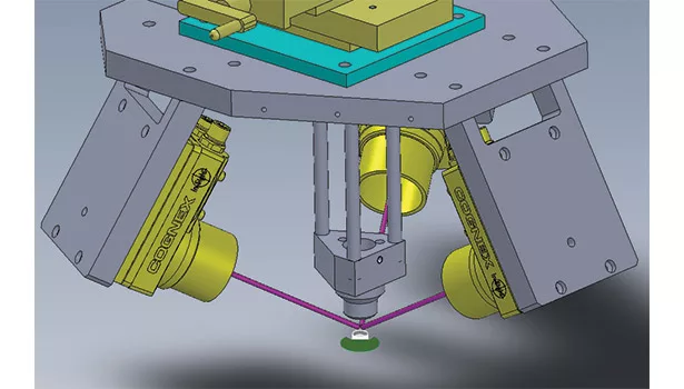
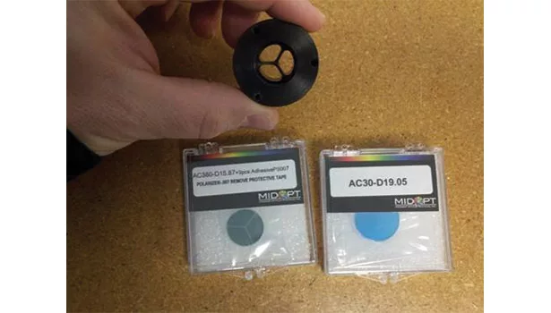
The cylindrical geometry of the object under inspection interfered with the ability to use just a simple 1D polarizer for a multiple camera system. Walker reduced glare by using a unique setup of polarizing filters that were made by Midwest Optical Systems (MidOpt). Three pie-shaped polarizers were fit into a peace-sign-shaped fiber optic end effector. The direction of polarization of these pie-shaped polarizers served to eliminate glare caused by both direct reflections of light and the Brewster effect of reflected light polarizations. This geometry of polarizers served to polarize the light source in such a way that benefits every camera inspecting the product. The cameras were additionally cross-polarized with PR032 polarizers from MidOpt.
Glare is eliminated completely by using the BP550 filter to eliminate any UV or IR light being generated from the Xenon light source. This filter was necessary because standard polarizer filters do not polarize light in this range of the spectrum. In addition, the AC380 filter from MidOpt was used as a protective surface for the end effector.
Filtering Improves Line Speed
The use of filtering made it possible to simplify the machine vision algorithm, particularly by reducing the amount of digital image filtering. This reduced inspection time from 85 milliseconds to 65 milliseconds, enabling a potential 31% increase in line speed to about 900 ppm, depending on the speed of the camera used. EPIC Systems has already installed six different similar systems for the client on six different lines, with different vision systems to match different line speeds. Walker has tested the algorithm on the Cognex 5600 In-Sight vision system, achieving an inspection time of only 38 milliseconds, which enables a production speed of 1,100 ppm.
In-Sight 5600 vision systems offer the same design as the In-Sight 5400 series, but with twice the processing speed and memory to perform inspections at higher line rates. The In-Sight 5600 product line includes standard (640 x 480) resolution and two-megapixel (1,600 x 1,200) models that deliver reliable performance in high-speed applications. All In-Sight vision sensors have an IP67 (NEMA 4) rating to withstand dust and wash down without an accessory enclosure.
In addition, a library of vision software for inspection, identification, measurement and alignment tasks is included. The vision systems provide rugged die-cast aluminum and stainless steel cases that can withstand vibration, sealed M12 connectors, and a protective lens cover for IP67- and IP68-rated protection against dust and moisture.
“Proper choice of lighting helps create more robust vision systems,” Walker said. “In this application, the use of filtering to improve image quality made it possible to reduce the number of false failures. The filters substantially reduced manual inspection time and made it possible to speed up the line.”
For more information, call (877) 264-6391, email pr@cognex.com or visit www.cognex.com. EPIC Systems can be found online at http://epicvisionsystems.com.
Looking for a reprint of this article?
From high-res PDFs to custom plaques, order your copy today!


