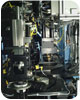
Test-Centric Assembly
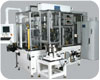
Eighteen-station assembly chassis optimized for test-centric assembly.
In-process testing minimizes rework and scrap costs.
A common but less satisfactory approach to machine building of test-intensive assemblies is to consider testing as an afterthought to overall machine design. This often means that the real testing requirements of an assembly and test application are misunderstood. This approach typically compromises Gauge R&R. In many cases, defective part problems are predominant and there is an inability to diagnose whether testing processes are lacking and creating erroneous defect readings or if real defects in the parts are at issue.
Hallmarks of test-centric assemblies are expert fixture design and integration of both hardware and software at the system level. Test-centric assembly refers to the entirety of the applications engineering knowledge base that enables testing experts with a singular focus on testing to improve production speed and yields in test-intensive operations.
This article reviews the general principles of test-centric assembly for manufacturers and machine builders more accustomed to streamlining assembly operations where testing is absent or plays a minimal part.
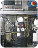
Fixture design is critical to test process integrity.
End of Line vs. In-Process Testing
In many manufacturing scenarios, there are considerable advantages to focusing on in-process (as opposed to end-of-line) testing. As a part or assembly is built, material and labor costs are constantly added. The total value of a production component is usually a function of its percentage completion, and includes both labor and material costs built into the item. If testing is integrated throughout an assembly, the costs of adding material and labor to defective production components can be avoided.Following are some examples of how costs for rework and scrap can be avoided by in-process testing.
- Functional testing to verify electrical, pneumatic and mechanical part characteristics before further assembly steps.
- Automatic resistance measurements in stations that follow the addition of coils, heaters or resistors.
- Leak test following ultrasonic welding of two plastic housings.
- Leak testing following spin riveting of a cover to a pump housing.
- Leak testing after the insertion of an “O” ring or other seal.
- Machine vision systems or probes used to ensure that parts are positioned properly.
- Dimensional gauging stations, especially after a crimping or staking operation.
- Electrical testing of continuity, voltage, current and contact bounce.
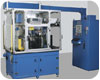
For better efficiency in test-centric assembly, testing applications engineers designed a standardized heavy-duty in-line chassis that allows a flexible workstation setup and retooling, including double dwell time at selected stations without slowing cycle times throughout the machine. These are typically small footprint machines, e.g., 40 inches (1,016 mm) x 90 inches (2,286 mm) long for 18 stations or 61 inches (1,549.4 mm) long for 10 stations. Assemblies can be made of multiple standard testing chassis, combining standard units end-to-end, side-by-side, or end-to side for assembly and test operations requiring additional stations. Servo drives allow one to optimize the transfer rate depending on part inertia (weight) without requiring any machine component replacements or mechanical adjustments. Individual station base plates are used to simplify adding, removing or retooling any station without disturbing the others. These standardized chasses for test-intensive operations accept a range of standardized tooling and robotics or customized equipment needed for other parts of the assembly process. What differentiates these test-intensive assembly chasses from power and free systems is twofold: 1.) the use of quick change fixturing and 2.) the ability to double up stations for greater flexibility and to reduce work in process (fewer pallets).
Test-centric assemblies can always be used to track the contents of each pallet and report to control systems on conditions of parts. Hence, the control system can identify the presence or absence of parts on a pallet, whether or not the part has passed or failed a test, and, in some cases, will identify if the part was tested yet. Different signaling systems gather this information, with the more sophisticated systems including a means of reading the pallet number so the system can track information on a particular pallet, in addition to identifying the status of the pallet contents.
Test-centric assemblies cannot only test and track parts, but handle rejected pallets as well. This can be done by having rejected pallets continue down the line but be ignored by succeeding operations until they can be unloaded at an intermediate reject position or immediately after testing. Rejects can then be sent to a parallel repair line. Whatever method is used, its objective is to avoid any further work on a rejected or defective part, which is the overriding advantage of in-process testing.
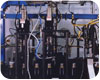
Test-centric assemblies have automatic defective parts removal.
Defective Parts or Defective Tests?
The inability to differentiate good parts from defective parts may be due to faulty testing methods, which are usually the result of an inadequate understanding of real testing requirements. An example is found in test results with insufficient signal-to-noise ratios. In leak testing, there are often problems with seal creep. Another example is in-process gauging stations that are insufficiently rigid or do not have the correct reference.The first considerations in test-centric assembly are: developing a thorough and detailed understanding of required testing accuracies; finding the best methods to achieve the required results; and obtaining a detailed understanding of how the tests actually proceed so that one does not unwittingly undermine the test process.
For example, in leak testing, the choice between methods is driven by a compromise between a leak detector’s performance and cost of purchasing a highly specified piece of equipment. Several methods could be used - simple pressure decay testing, differential pressure decay testing, mass flow leak testing, and helium mass spectrometer testing. The lowest cost method - pressure decay testing - actually has lower initial costs for fixtures, etc., but may be more costly due to longer test cycle times. In addition, it is unsatisfactory for testing for small leaks under 5 sccm. Differential pressure decay testing methods are superior to simple pressure decay testing for small leak testing or for testing at high pressures, but are similarly inadequate for testing parts where temperature compensation is an issue. Both pressure decay and differential pressure decay test methods involve increased cycle times compared to other dry air test methods.
(Note: The most common mistake made by those without testing expertise is to select the least expensive instrument. However, this does not imply that higher cost test methods are directly correlated to the best test technology choices. High-cost helium testing, especially costly in the current context of rapidly rising helium prices worldwide, is rarely justified except for aerospace and similar applications where potentially hazardous gas leaks less than 0.01 sccm need to be detected. In most applications requiring detection of low leak rates, the lower-cost mass flow testing method using customized sensors is preferable, since it has the shortest possible testing times, can readily compensate for temperature, and it delivers the best accuracy for applications where testing is required at 0.05 sccm or larger.)
The details of how a test is performed can be all important in determining if the testing process is adequate. Often, this means having the ability to test the test process as testing proceeds. In downstream mass flow testing, for example, where there is zero pressure from atmosphere, it is not possible to know if a valve used in testing is working or not unless extra steps are taken. A zero-leak measurement could otherwise be due to a dysfunctional valve or a line being plugged. For that reason, accurate downstream mass flow test methods will always use a bias leak that verifies that the entire system is working and that the test circuit’s integrity is not compromised. A bias leak is simply the introduction of a known leak as a self-check of the testing system. If valves are not operating properly and test seals are insufficient the bias leak will not measure as a leak, indicating that remedial actions on the test system need to be taken.
Similarly, test systems should be frequently and accurately calibrated and validated. Mistakes often occur due to reliance on antiquated mechanical calibration methods that have inherent limitations (such as pneumatic valves and other moving parts that can stick or wear, and/or small orifices that can clog). Today’s test-centric assemblies rarely use human-error-prone mechanical calibration methods; instead, they rely on electronic technology for calibration and validation of testing. These electronic test methods are not only more reliable but are fast, which is one of the reasons why test-centric assemblies generally have significantly higher yields and shorter test times.
Custom software for test-intensive assembly helps cut costs.
Differences in Fixtures for Assembly vs. Testing
It often comes as a surprise to those familiar with building standard assemblies that the fixtures they take pains to create for fastest assembly throughput often have quite the opposite characteristics of what one would want for fail-safe testing in most assembly and test operations. This is why one is best advised to consult with applications laboratories dedicated to developing best-match test processes to help with test fixture designs.For example, if you have a part that is driving a screw you generally want a lot of float. However, to leak test that part, you would have to seal it on dead nuts so the sealing location would interfere with other steps of the assembly operation. Hence, it’s best not to use the same pallets during leak testing as in other phases of assembly and testing.
In dry air leak testing, another issue is part damage during sealing. A simple clamp and cylinder could eliminate deflection of a part during testing - but can also crush the part. In addition, if you have a weld and the part is operated under pressure, you must ensure that if the weld opens up you have a leak to atmosphere. If you are restraining the weld motion, you are restraining the leak.
As another example, if a fixture has threads and you are trying to pull down to a certain vacuum level, air will escape as you pull the vacuum down if the threads aren’t slotted. This could appear as a gross leak or prevent the desired vacuum level from being achieved and make it impossible to do reliable testing with that fixture design. Thus, expert fixture designs for dry air leak testing must manage several factors: the part must be stationery; the part cannot be crushed or damaged; and the fixture design cannot mask leaks.
From a fixturing perspective, helium leak testing has another set of challenges. In helium testing, no helium can be trapped or retained in seals. In helium or any tracer gas application, what happens to tracer gas at the end of the test is critical; if you have any trapped test gas staying around after the test sequence, it contaminates the following test. This is not the case with dry air testing. On the other hand, deflection issues are less critical in helium leak testing than in dry air testing. One needs to understand the different requirements of each test method in relation to fixture design and how improper designs will compromise that specific type of testing.
In many assembly and test applications, there is also a need to orient the part being tested in the same orientation that it will have when in use in the field. The applications where this is an overriding feature of fixture design are quite diverse - from automotive valves that are referred to as ‘true car position’ when functionally tested to respirator components in the medical field.
In some instances, assembly and test fixture designs must also take into account and simulate the parts to which parts are to be joined. This is very predominant in leak testing medical devices. For example, if the device has an O-ring, you will generally want to mimic the mating surface. While leak testing a transmission casting for an automotive assembly, you would try to mimic the paper gaskets that will be in use in the field, as opposed to actually using paper gaskets since these wouldn’t hold up during the testing process.
Fixture design is often mediated by how automated the overall assembly and test operation is and at the specific testing stations. In manual systems, the sealing and fixturing may be more difficult because of ergonomic issues. Clearance for loading and unloading may be an issue. Poka-yoke (a Japanese term meaning mistake-proofing) considerations are such that often a fixture design will anticipate human errors of placing wrong parts in the testing stations. A poka-yoke informed fixture design will make sure that only parts with the correct dimensions will be tested.
This is only a brief discussion of some of the factors that testing applications engineers must consider. Since fixture design can make or break your assembly and test solution, it is generally advisable to enlist only testing engineers with experience in building many turnkey testing solutions. One needs a nuanced understanding of leak test and functional test requirements to bear on fixture designs that allow superior test instruments to deliver their promised performance. In fact, the growing use of off-the-shelf fixtures such as expandable seals is a reflection of how little the real requirements for fixture design during testing are understood. Reliable and reproduceable gauges almost always require custom fixture designs given the unlimited variety of geometries in parts that are tested.
Seventy percent reduction in test cycle times is standard in test-centric assemblies.
Generic vs. Customized Software/Instrumentation
There are no one-size-fits-all generic testing solutions. Taking short cuts by selecting the lowest cost instrument from the shelf and placing it into assemblies rarely achieves Gauge R&R in acceptable ranges because the test sensors and software programming are not well-matched to application requirements.In fact, most of the assembly and test solutions that do not meet the test-centric assembly standard are easily identified by their use of one or another generic off-the-shelf software packages. This probably reflects the fact that most assemblies have been configured by machine builders with little training or inclination to master software engineering. In fact, test-centric assemblies require expertise in both mechanical engineering and software engineering.
In most cases, custom software for test-intensive assemblies is less expensive than a generic off-the-shelf application because it is designed to meet real business needs and does not include superfluous program features and functionality. Moreover, many general applications are not especially easy to use, or do not reflect the real data handling requirements of the application.
Most test applications require software that works in real time, for example, which is usually not the case with off-the-shelf packages. It is important to have the means to view real-time traces of test instrumentation transducers’ performance, as opposed to simple test cycle times. Slower and less detailed applications do not process data quickly enough to provide for meaningful test control and/or test method calibrations. If the required data analysis is more complicated than generating a simple line graph, the off-the-shelf software packages that are commonly used similarly fall short. The best-in-class custom software for test-centric assemblies will also automatically calculate R&R percentages based on the number of trials performed.
How networks are built is also important in fully integrating testing into assembly operations. When there are steep requirements for testing, there is a lot of data that typically has to be processed and also sent to a plant-wide network. BUS compatibilities need to be considered.
State-of-art test-centric assemblies have Ethernet capabilities that allow the huge datasets from intensive testing to be distributed to plant-wide networks for analysis. Internet-based remote diagnostics are another feature of the best-in-class test-centric assemblies.
Custom software development for test-centric solutions starts with identifying business goals as to how the data and information garnered during testing will be used not just in initial production but also during the entire lifecycle of the product being produced in the assembly and test operation. This is of growing importance to the many industries that now want processes to attach data to products from cradle-to-grave to assist with recalls or reducing time-to-market in new product development cycles.
Multiple Cost Savings
A less-than-ideal assembly and test operation is one where the machine builder defines testing gauge R&R in terms of those proffered by the manufacturers of the test instruments. Gauge R&R of the entirely assembly and test solution is what counts, and this is what must be guaranteed to users of the test-centric assembly and test solution. This explains why the most savvy machine builders around the world are now incorporating applications engineers with a sole focus on testing into their project development teams.The improvements to be expected from a test-centric assembly approach are not trivial. Leak test and functional test cycle times can be decreased 25-70% in the best-in-class examples, and yields increased proportionally.
There are numerous cost-savings from implementing a test-centric assembly approach. First, greater returns from higher yields in test-centric assemblies can be achieved by using better fixture designs, and customized test instruments, and related software and high throughput chasses designed for test-intensive operations. Second, in-process testing cuts the added costs for finishing products that will ultimately be deemed defective. Third, defective parts are not misclassified as “good” parts and returns are minimized. Finally, time-to-market for new product development can be decreased by as much as 10% by mining extensive test data from assembly and test operations.
For more information on InterTech instruments, Applications Lab, and consulting services, contact Gerald Sim, e-mail gsim@intertechdevelopment.com, phone (847) 679-3377 or fax (847) 679-3391.
Looking for a reprint of this article?
From high-res PDFs to custom plaques, order your copy today!


