Through Thick & Thin
For the estimation of the mechanical behavior of adhesively bonded joints, simple polymer samples (e.g., dog bone test) are of limited use, as chemical composition and surface pretreatment of the adherends cannot be considered. This is of special importance if substrate-sensitive adhesives, such as anaerobics, are applied. In technical practice, joints should, wherever possible, be loaded in shear; therefore such destructive lap tests have established themselves as the standard in-situ test methods.
Thick- and Thin-Adherend Tensile-Shear Tests
Shear tests, like the napkin ring torsion technique with butt-bonded hollow cylinders according to ISO 11003-1 (ASTM E 229-92) or the Iosipescu method with notched substrates1, are seldom used in adhesive technology. This is also true for double-lap joints, which are difficult to prepare and cannot avoid principal problems such as differential sample straining. Industry demands simple experimental procedures; thus, static single-lap tests with plate adherends represent the preferential methods.
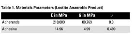
For the design of a joint, the elastic parameters (two out of Young's modulus E, shear modulus G, and Poisson's ratio v) and - in some cases - the failure stress and strain are usually required. For the determination of these characteristics, the thick-adherend tensile-shear test according to ISO 11003-2 (ASTM D 3983-81) is often applied. Substrate deformation can be taken into account by appropriately attached extensometers2 and numerical correction.3
FE Modeling
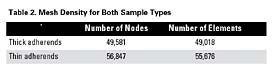
The commercial FE code MSC.Marc is used. Figures 1-2 show the sample models with the definition of coordinates, boundary conditions and applied loads, as well as mesh details for both single-lap joints with thick and thin adherends, respectively. With a glue length of 12 mm and specimen width of 25 mm, the glue surface area amounts to 300 mm2. The thickness of the adhesive layer (bond gap) equals 30 µm, which is typical of anaerobic products. The essential difference between both types of test joints is the substrate thickness: 12 mm (thick adherends) and 1.6 mm (thin adherends).
FE Results
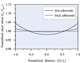
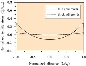
The computed stress curves are normalized with respect to the mean shear stress, tave. In Figures 3-5, la denotes the glue length (12 mm). For all calculated stress components, the edge raise in the case of the joined thin substrates is much higher if compared with thick adherends.

Experimental Results
Single-lap tensile-shear tests with thick and thin S235 adherends are performed at room temperature (296 K) according to ISO 11003-2 with stepped substrates4 and ISO 4587, respectively. The anaerobic product defined in Table 1 is applied with a 30 µm gap. Results are shown in Figure 6. In agreement with the findings of the FE simulation presented previously, the measured fracture strength of the adhesively bonded thick substrates (ISO 11003-2) is more than two times higher than the one of the glued thin adherends (ISO 4587).Conclusion
The present comparison of the static single-lap tensile-shear tests according to the standards ISO 11003-2 and ISO 4587 indicate that adherend thickness considerably influences the effect of differential straining in the substrate and thus the uniformity of the stress state. As a concrete example, structural steel specimens (S235) joined together with an anaerobic adhesive (30 µm gap) are chosen. The performed finite element simulation confirms that for the thick adherends (ISO 11003-2) a much more homogeneous stress distribution across the bond line exists, whereas the thin plane sheet assembly reveals a high stress increase (particularly tensile component sx) at the edge of the joint and compression in the middle region. As an important consequence, under the same test conditions, the experimentally determined fracture strength of glued thick stepped substrates exceeds the one of thin plate samples by a factor greater than two.Simplified performance is the main advantage of the ISO 4587 thin-adherend tensile-shear test. It is widely used, so a huge variety of measurements is available in literature. However, the obtained data has very limited connection to the desired intrinsic adhesive parameters. As this article emphasizes, realistic shear characteristics, necessary for engineering joint design, can only be determined by applying the ISO 11003-2 thick-adherend test.
For more information on lap shear tests, contact Dr. Jürgen Gegner, SKF GmbH, Ernst-Sachs-Str. 5, 97424 Schweinfurt, Germany; or Dr. Andreas
Looking for a reprint of this article?
From high-res PDFs to custom plaques, order your copy today!


