Lighten Up
Manufacturers are striving to eliminate inventory, use floor space efficiently and improve throughput. The long cure and fixture times required for some adhesive systems are not always compatible with these goals. However, adhesive systems that cure very rapidly introduce their own processing dilemmas and can contribute to higher levels of scrap and adhesive waste.
Light-cure adhesives help manufacturers to resolve this tradeoff by remaining liquid until exposed to light of the proper wavelength and intensity. Their long open time allows for positioning of parts, while their ability to achieve complete cure within seconds can significantly improve part flow through manufacturing processes. Advances in light-cure technology, particularly the availability of LED-based light sources, have lowered costs and significantly expanded the options available to manufacturers.
Introduction to Light-Curing Adhesive Technology
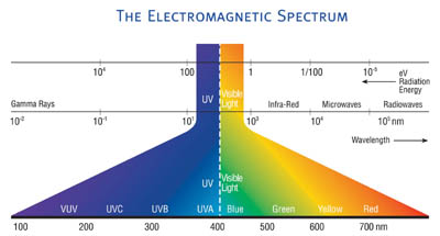
Light-cure adhesives solidify upon exposure to the appropriate wavelength and intensity of ultraviolet (UV) or visible light, and offer a number of processing benefits. These adhesives deliver long open times for the positioning of parts, yet achieve complete cure in seconds, a significant benefit for manufacturers looking to improve part flow through their manufacturing operations. As these materials process very rapidly and cure in seconds, they minimize work in progress. Light-cure adhesives contain no solvents and have no potlife limitations, and their associated cure equipment requires far less space and energy than conventional heat-cure ovens.For an adhesive to react to UV or visible light, a photoinitiator must be present in the formulation. Light from a suitable source causes the photoinitiator to fragment into reactive species, initiating a rapid cure process. By definition, UV light is the region of the electromagnetic spectrum from 40 to 400 nm, while visible light is the region from 400 to approximately 800 nm (see Figure 1).
Light-Curing Equipment
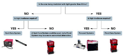
Light-cure equipment is defined by the type of light source and its part handling capabilities. While certain equipment holds parts immobile under the light source, other equipment moves parts along under the light source during cure. All light sources can be incorporated in static or mobile equipment, depending on the application requirements.There are three broad categories of light sources: spot-cure systems, flood systems and focused systems. Figure 3 displays a decision tree for selecting between these three types of systems.
Spot-cure systems are useful for focusing high levels of light energy into small areas. They can consist of a mercury arc lamp focused into a light guide or an LED source focused through a lens. The light guide used with the arc lamp source is a liquid filled tube approximately 0.5 inches in diameter and several feet long. Light energy travels through the tube to reach the part.
Flood systems are more useful for irradiating large areas, but have lower irradiance. They consist of a bulb with a parabolic reflector that evenly distributes light over a large work area, typically in the range of 8 by 8 inches. By moving parts through the band of light under the bulb, focused systems can irradiate large areas with high-intensity light. These systems feature a higher output bulb held in an elliptical reflector, and deliver a very high intensity band of light focused under the bulb.
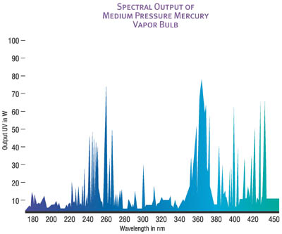
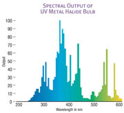
Spot-cure systems typically use high-pressure mercury arc light bulbs, or LEDs, while flood-cure systems often use metal halide bulbs. Focused-cure systems use a variety of different light bulbs. Understanding the difference between LEDs, mercury arc lamps and electrodeless lamps is crucial to selecting the proper light source for an application.
Spot-cure or wand systems focus very high levels of light irradiance in a small area, enabling them to rapidly cure an adhesive without exposing the entire assembly to ultraviolet light. This focusing capability minimizes heat degradation, reduces space requirements, and decreases ventilation and shielding requirements for the light source.

As traditional mercury arc bulb-based spot-cure systems age, longer cure times are required to deliver the same total energy, imposing limitations on the production rate and increasing production costs. In addition, peak irradiance will eventually drop so significantly that depth of cure, surface cure and minimal cure speed requirements will be unachievable. At this point, the bulb, which typically makes up 5-10% of the cost of the entire wand system, will have to be replaced, impacting the cost of the light-cure system.
Electrodeless bulbs consist of a quartz tube that is filled with chemicals that are excited to a plasma state by way of focused RF energy from a magnetron. Since there are no electrodes to degrade, the output of these types of systems remains more consistent over time, and the bulbs typically last at least two to three times longer than electrode containing bulbs.
Industrial use of light emitting diode (LED)-based light-curing equipment has been limited by the power and output spectra available. Recent developments in cooling and LED technology have eliminated these barriers and opened the door to widespread use of LEDs in industrial manufacturing operations. Rather than using current to bring mercury into a plasma state, the LED emits light through the movement of electrons in a semiconductor material. LEDs are more efficient than standard light sources and give off very little heat. They have a longer life than standard light sources (greater than 50,000 hours vs. 2,000 hours for typical mercury arc bulbs), are less expensive, and do not degrade in output over time.
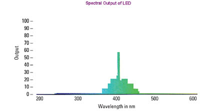
LED output range is typically focused in a very narrow range of wavelengths when compared with other light sources. LED systems are available with spectral output focused in the lower limit of the visible light range, which coincides with the absorbance range of many visible light-curing adhesives. By providing high output in the visible range, these systems allow end users to obtain the benefits of high-output light sources while completely eliminating human exposure to UV light.
Since LEDs do not have lower wavelength output, they must have sufficient irradiance to achieve surface cure of adhesives - particularly with acrylic adhesives that are susceptible to poor surface cure due to oxygen inhibition. By using innovative heat-transfer technologies and marrying the LED with adhesives that are reactive at the proper wavelength, manufacturers can use light-curing devices that are less expensive, longer lasting, and more energy efficient. These devices also do not emit infrared radiation that can potentially damage heat-sensitive substrates.
The low power consumption of LEDs allows hand-held, battery-powered units to be designed to deliver a watt of light irradiance. This portability permits easy positioning of the light source in confined areas and expands its use beyond typical applications.
Monitoring Light-Cure Processes
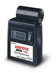
Light-cure processes are easy to control with regular monitoring and maintenance. Radiometers are used to measure the irradiance of a light source, and are available in a variety of configurations to meet the needs of different cure processes. With spot-cure systems, radiometers such as the one shown in Figure 5 are typically used. The tip of the spot-cure system is inserted into the end of the radiometer to measure wand irradiance. Radiometers must be calibrated on a regular basis, typically every six to 12 months, in accordance with the manufacturer's instructions.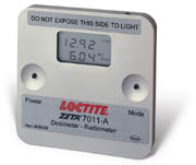
Maintaining and Troubleshooting Light-Cure Processes
To maintain a light-curing system, the user should accurately measure and record the baseline irradiance and the total energy of the system when it is working properly. When documenting irradiance, the following information should be recorded so that the measurement can be successfully repeated in the future.
- Type of radiometer used and its calibration date - for most consistent results, use the same radiometer for all future readings or at least the same model of radiometer, as different models can yield different results.
- Wavelength or UV region where the measurement is being taken - as the output curve for any light source varies with wavelength.
- Exposure time - to achieve the same result if a conveyor is being used, record the belt speed and the distance from the light source to the conveyor belt.
- Type of lamp used - if lamp types are inadvertently changed, the cure characteristics of the system may change drastically even if irradiance readings at a certain wavelength do not change.
- Position of the radiometer relative to the light source - the distance between the radiometer and the light source dramatically affects irradiance.
- Location of the radiometer with respect to the bulb for focused systems - output directly under the bulb will be much greater than output a few inches away from the centerline of the bulb. If possible, the radiometer should be placed in a position that closely mimics the position of the part under the light source.
For electrode-based lamps where degradation of the bulb over time significantly affects light-curing system performance, determine the minimum irradiance that will produce satisfactory parts. Change the bulb once its output has degraded to the point that it cannot provide this level of irradiance.
Prior to changing the bulb, inspect other aspects of the system that may be contributing to reduced output. For example, on focused systems, contaminants from the work environment can accumulate on the reflectors, making regular cleaning important. The filter glass between the metal halide light source and the curing area on flood systems should be cleaned of contaminants as well.
On spot-cure systems, outgassing products from the adhesives may accumulate in a thin layer on the tip of the wand. Regular cleaning of this tip can dramatically improve light output. Also, the spot-cure light guide and any filters between the light source and the light guide can degrade.
With LED-based systems, the LED is unlikely to degrade. As there is no light guide present, any degradation in system output is likely due to the accumulation of contaminants on the wand tip.
If light-cure equipment is producing output similar to the working baseline but there are still problems, other factors must be considered. If using an adhesive, check the shelf life and storage conditions of the material and evaluate another lot to see if the problems are lot specific. Also be sure that the ultraviolet light transmission characteristics of the substrates have not changed; for example, different grades of polycarbonate can vary dramatically in their ability to transmit ultraviolet light even though they may not differ in appearance.
For more information on light-curing systems, contact Henkel Corp. at http://www.henkel.com .
Looking for a reprint of this article?
From high-res PDFs to custom plaques, order your copy today!


