Automated Flow-in-Place Gasketing Material and design considerations
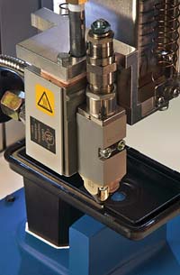
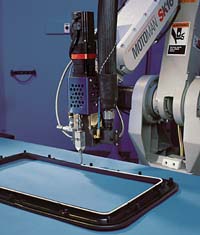
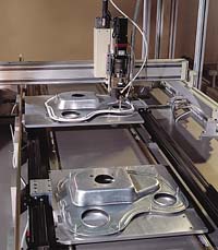
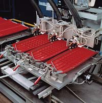
Automated flow-in-place gasketing refers to the use of industrial automation such as XYZ tables and articulated arm robots to apply a variety of flowable materials to act as a gasket on different substrates.
Traditionally, gaskets have been made of die-cut or foam tape materials that are manually placed on the substrate. Manual application of gaskets may raise issues concerning the labor cost of applying the gasket, production speed and waste generation for some applications. Hundreds of manufacturers have resolved these and other concerns by converting to flow-in-place gasketing.
New material technologies and formulations have been developed to offer expanded performance characteristics for the materials available for automated flow-in-place gasketing. With these new material choices comes some confusion. What is the proper material for a given application? How is this material best applied?
Experience has shown that converting to or starting an automated flow-in-place gasketing application can be broken down into a six-step process.
1. Information gathering/process assessment
2. Material and automation selection
3. Gasket design
4. System design
5. Prototype testing
6. Installation/service
A closer examination of steps 2-3 reveals many of the common considerations involved when examining the plausibility of automated flow-in-place gasketing.
Material Selection
A variety of materials have found use in automated flow-in-place gasketing, including thermoplastic hot melts, PUR hot melts, polyurethanes and RTV silicones.Gasketing materials may be applied in a solid state or they may be mechanically foamed. Certain physical properties of materials may be enhanced from a gasketing perspective by foaming, including the following.
• Reduced force to compress
• Reduced weight (density)
• Greater deflection under fixed load
• Reduced cure time (for curable materials)
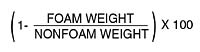
The level of foam is defined in terms of percent density reduction, the percent of material displaced by inert gas, calculated by: (1-Foam Weight divided by Nonfoam Weight) x 100.
When considering the feasibility of automated flow-in-place gasketing, many questions arise pertaining to the physical characteristics required of the gasket. These physical characteristics and end-use conditions of the gasket have a direct bearing on material selection. Following are some requirements that are often considered.
• Cure time (and/or handling time)
• Compression set resistance
• In-use temperature conditions
• Resistance to various fluids
• Durometer (hardness)
• Adhesion to substrate
In addition to the gaskets’ physical characteristics listed above, other factors such as cost, color and appearance will be taken into consideration when evaluating the flow-in-place concept.
A major factor in determining the feasibility of an automated flow-in-place gasket is the cure time required for the gasket. A die-cut or foam tape gasket is complete immediately after placement. A flow-in-place gasket will have some cure time consideration.
During this cure time, the parts may have to be racked — or at least handled carefully — until the gasket has acquired sufficient cure to allow for packaging or assembly. Taking a closer look at the different material types relative to cure time is important.
Thermoplastic hot melts probably offer the fastest set time. These materials do not cure in the sense of most other flow-in-place materials. Thermoplastic hot melts transition from a solid to a liquid for application with the addition of heat. After application, the materials are cooled and return to a solid state. These materials can be returned back to the liquid state by heating again. These materials reach their final gasketing properties as soon as they cool to room temperature. Depending on the bead size, this can take a relatively short period of time — only a minute or two.
Curable, warm-applied specialty gasketing materials offer the next stage in cure possibilities. These materials are warm applied, like a hot melt, and they can be handled as soon as the bead cools and the material turns to a solid (like a hot melt). Unlike hot melts, these materials then undergo a moisture cure phase, where the material reacts with ambient moisture to crosslink. After this stage, these materials cannot be remelted. After the curing phase, these materials will acquire enhanced performance characteristics relative to hot melts.
Moisture-curable materials such as RTV silicones and urethane materials rely on atmospheric moisture to cure. These materials are applied in a liquid to paste-like state. They typically skin over relatively quickly and then proceed to cure from the outside in. Gaskets can typically be handled but cannot be compressed until a full cure is achieved.
To respond to the need for faster cure times, some manufacturers have used humidity and/or heating chambers that the gasketed part passes through after application of the gasket. Also, certain materials are available with an enhanced cure mechanism, such as UV curing. These materials are subjected to high intensity UV light to affect a faster cure.
Another important characteristic of a gasket is compression set resistance. This is the ability of a gasket to recover to its original shape after being compressed. This is a particularly important characteristic for a gasket that is exposed to repeated cycles of compression and release.
Thermoplastic hot melts are very limited in regard to compression set resistance. These materials will take almost a complete compression set, even when exposed to compression at room temperature. For this reason, thermoplastic hot melt materials are typically not considered as candidates for compression gaskets. If, however, a one-time seal is required, and ambient conditions do not exceed the softening point of the material, thermoplastic hot melts may be considered.
The curable warm-applied gasketing materials improve on the thermoplastic hot melts in regard to compression set resistance once they have achieved a cured state. These materials may take a 20-40% compression set at 80 degrees C, and show single digit compression set figures at 40-50 degrees C.
Silicone materials will show respectable compression set resistance figures even at high service temperatures. Compression set may be in the range of 15-20% at 150 degrees C.
This characteristic is closely allied with the compression set resistance. Typically, percent compression set is checked at the gasket service temperature. Ranking the materials from best to worst relative to temperature resistance (both elevated and depressed temperatures) generally reveals the following.
• RTV silicone
• Warm-applied curable gasketing compounds
• Silicone component urethanes
• Thermoplastic hot melts
Depending on the application, a flow-in-place gasket may come into either intermittent or continuous contact with a variety of engine fluids, cleaning fluids or solvents. This contact may be at room temperature, elevated temperature or at depressed temperature. Because of the variety of fluids and conditions possible, it is generally advisable to perform specific testing on any candidate materials. Curable flow-in-place gasketing materials generally offer good stability when exposed to various fluids. Silicones in general are very chemically inert substances that offer good resistance to many fluids. But even on the other end of the spectrum, thermoplastic hot melts have passed specific automotive test specifications for gaskets including sections detailing contact with various automotive fluids. Specifically, GM3628M specifies compatibility with the following fluids: naphtha, aliphatic hydrocarbon with emulsifier, 50/50 isopropanol/water, windshield washer fluid, car wash solution, ethylene glycol and 75% naphtha/25% 1,1,1-trichloroethane. This specification is met by several thermoplastic hot melts.

Different flow-in-place gasketing materials yield different durometer readings that may be called for in a specific gasketing application. Mechanically foamed or chemically foamed materials can be particularly useful in this regard, as the level of the foam can be adjusted to yield the required gasket durometer. Some general ranges for gasket durometers for the classes of materials are shown in Table 1.
Adhesion to the Substrate
As with resistance to various fluids, because of the range of substrates that can be gasketed, and the variety of flow-in-place gasketing materials available, it is not practical to try to list all compatible combinations or potential problem combinations. Adhesion to the substrate requires specific part testing of the substrate to be gasketed and the selected flow-in-place gasketing material. If adhesion is found to be inadequate, several techniques have been used in regard to surface preparation to enhance adhesion. These include cleaning and/or priming of the substrate, and surface treatments such as corona discharge or flame treatment of low surface energy plastic substrates.
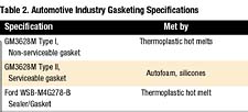
Table 2 lists some specific automotive industry gasketing specifications, and the types of materials that meet those specifications. This list is not intended to be all-inclusive.
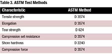
Material suppliers usually report a variety of physical data on their materials. They typically follow American Society of Testing Materials (ASTM) methods. Some of the common characteristics and the associated test methods are listed in Table 3.

Design Options for Flow-in-Place Gasketing
After a material has been selected for a flow-in-place gasketing application, the project moves to the gasket design phase. Many of the gasketing material selection criteria cited previously also have an effect on gasket and/or part design. While the compression set characteristics of a target material may be fixed, design considerations such as designing parts to limit the amount of compression can greatly influence gasket performance. Common design factors that can be considered that have an impact on gasket design include the following.• Amount of compression
• Geometry of the sealing bead
• Sealing gap variations
• Design for manufacturing
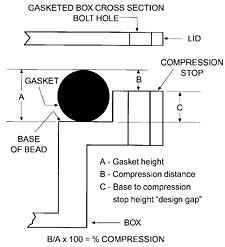
Experience has shown that most compression gaskets perform best at 30-50% compression. At less than 30% compression, sealing forces may not prove sufficient and irregularities of the part may leave leak points. At greater than 50% compression, the tendency of many materials to take a higher compression set increases. Gasket height and design gap determine the amount of compression. Design factors such as built-in compression stops help ensure that compression of the bead falls within accepted norms.
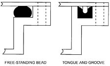
Design consideration involving the geometry of the sealing bead typically involves the decision to allow for a freestanding bead, or a bead in a groove. For moisture-curing materials, a freestanding bead will typically cure faster, as the bead is exposed on three sides. A bead in a groove is exposed on the top only. But a groove into which a gasket is placed can reduce the amount of gasketing material required. This is particularly true with low-viscosity, flowable materials. A groove will contain flowable materials, and allow bead height to be built without having the material flow out excessively.
Sealing Gap Variations
The total of all factors affecting variation of the gap, such as warp, bowing between fasteners and tolerances should be limited to 20% of the bead height or less. This helps to ensure that the compression falls within the desired 30-50% range at all times.
Design for Manufacturing
Designers should consider how production might be affected by the part design and the equipment needed to dispense the required flow-in-place gasket. Generally, the nozzles used to dispense gasketing materials are custom made for the application. Longer and thinner nozzles lower the potential flow rate of the material. A low flow rate can translate into a lower production cycle rate. Multiplying dispense stations can compensate for a low flow rate, but this solution increases the cost and complexity of a system. Nozzle access of a width double the bead size should be left centered over the dispense path. Also, any projections more than 1 in. high should be at least 6 in. from the dispense path. This will allow for a short nozzle and provide for clearance of the dispense head assembly.
Summary
Automated flow-in-place gasketing has become an accepted alternative to die-cut gasketing in numerous applications. When investigating the option of converting to, or starting, an automated flow-in-place cell, it is important to follow an established order of operation to minimize the process. Two steps to consider in the process are material selection and gasket design considerations. Performing these steps, along with the others, will help make the process more controllable and lead to a successful outcome.For more information:
For more information about automated flow-in-place gasketing, contact Nordson Corp., 11475 Lakefield Dr., Duluth, GA 30097-1511; phone 800-683-2314; fax 866-667-3329; or visit www.nordson.com.Looking for a reprint of this article?
From high-res PDFs to custom plaques, order your copy today!


