Case Study
Achieving Net-Positive Operations in Adhesive Tape Manufacturing
An air pollution control system designed and installed for a major tape coating line exemplifies how the best economic solution can also be the best environmental solution.
As manufacturers in the adhesives sector increasingly champion their roles as environmental stewards, their focus extends beyond the monetary benefits of immediate operations such as a reduced downtime, fuel cost, and waste disposal fees. Instead, the currency of environmental, social, and governance (ESG) factors comes to the forefront, and the lasting environmental impacts that manufacturers’ decisions will have for generations become of equal or even greater importance.
As more manufacturers across the adhesives and sealants industry embrace sustainable manufacturing processes, they are finding their decisions are also improving their financial bottom line. There does not need to be a trade-off, and green manufacturing is proving to be a win-win.
Tape Manufacturing Challenge
A large manufacturer of specialty adhesive tapes needed to replace its air pollution control equipment, which was over 20 years old, and the company had several goals. The equipment needed to comply with new local regulations and the U.S. Environmental Protection Agency’s (EPA) stringent code requirements for volatile organic compound (VOC) emissions. The company also wanted to achieve a higher destruction rate efficiency (DRE) and minimize fuel consumption compared to the levels in the current system.
Additional requirements included a low-maintenance design that performed with minimal need for cleaning downtime and could withstand the harsh operating conditions associated with adhesive processing lines for decades to come. The tape manufacturer was also looking for a customized system that could achieve as close to net-zero operations as possible.
Prior to the tape coating process, the backing material is not yet in the form of narrow, long strips; it is still a wide roll consisting of a base fabric, plastic film, or other material. A thin layer of the adhesive substance is then applied or transferred onto this large roll with an organic solvent. From there, the coated backing with the adhesive passes through the process heating equipment (a drying tunnel), where the solvent evaporates. The adhesive tape coating becomes solid and is connected firmly with the backing after the drying process, and the entire large strip is then rewound for final cutting and production packaging.
Proprietary adhesive mixtures comprise a variety of synthetic chemical substrates with varying characteristics and benefits that are designed to suit a wide range of specific applications. These unique chemical compositions bring unique sets of VOCs and toxic chemical byproducts that are often released during the tape manufacturing process. This specific tape application uses a proprietary adhesive with a polyurethane and isocyanate base.
It is during the drying process and subsequent solvent evaporation phase where large quantities of toxic VOCs are created and need to be contained and destroyed. A properly designed air pollution control system is critical for tape manufacturers to keep their employees and surrounding communities safe and healthy while staying compliant with regulatory environmental standards. The proposed solution was an integrated air pollution system, including comprehensive heat recovery and operating conditions for maximum thermal efficiency, to ensure the destruction of process emissions and provide 100% regulatory compliance.
Customized Solution
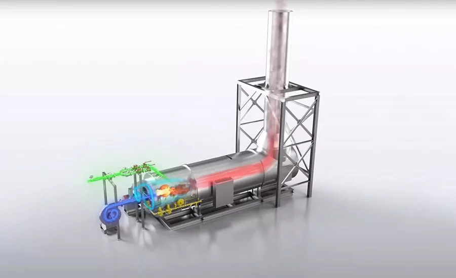
After much analysis, including process calculations and flow simulations, the Epcon engineering team selected and designed a 1,000 standard cubic feet per minute (SCFM), direct-fired thermal oxidizer (DFTO). The unit works in conjunction with a waste heat boiler that offers 97%+ heat recovery and is equipped with a bypass to atmosphere to control the steam pressure and volume, as well as a secondary heat exchanger.
A direct-fired thermal oxidizer was the most suitable choice for the tape manufacturer’s operation for numerous reasons, including the high VOC content and low flow rate of the process.
Because the adhesive process stream is filled with sticky resins, the option of using a more traditional regenerative thermal oxidizer was not feasible. The configuration and design of those systems includes purge choke points and ceramic fiber media beds that would easily become clogged with the sticky residuals from the adhesive process. This would result in the need for extensive cleaning, as well as frequent media replacement.
The DFTO was also the most suitable choice because of the high VOC content and low process flow rate. The gas stream from the drying process has a flow rate that fluctuates between 500-600 SCFM and is laden with approximately 50 lbs of VOCs to oxidize per hour. The composition is primarily of acetone with traces of heptane, hexane, and other solvents commonly found in adhesive gas streams. The exothermic reaction when these VOCs are oxidized in the chamber has a value of 500,000 British thermal units per hour (BTUH). This additional heat allows the process inlet temperature to be much lower, with a minimal need for pre-heating.
One of the key challenges is to ensure explosive safety measures, since these complex gases in high concentrations and low volumes require high temperatures to achieve complete oxidization levels. The safety aspects of the DFTO design needed to be comprehensive, as the process stream had a high lower explosive limit (LEL). Flame arrestors and detonation arrestors are used throughout to safeguard against explosions and ensure that there is no flashback hazard.
VOC destruction takes place within the combustion chamber. Time, temperature, and turbulence (known as the three Ts) are the necessary ingredients for successful oxidation. The size and design of the chamber were custom engineered to ensure that all three Ts are sufficiently present and the target DRE is achieved. A residence time of 1.0+ seconds at operating temperatures of between 1,500-1,600°F is key for the specific VOCs present in the process stream to achieve the desired DRE of 99% non-methane hydrocarbons (NMHCs) for maximum VOC loading peaks.
The most challenging metric is getting the turbulence in the process flow just right in order to achieve the desired temperature profile evenly throughout the chamber. To achieve this, engineers utilized a proprietary venturi design to create the sufficient levels of turbulence required for adequate mixing of the pollutants and oxygen molecules.
The existing process flow requires additional dilution air to allow for complete and proper oxidation. This not only supplies the process with the oxygen to ignite and combust the VOCs in the chamber, but it also reduces the process flow’s LEL down from 40%. The LEL sensors detect the VOC concentration, and actuators are programmed to automatically adjust the openings of various dampers to enable continuous air flow and maintain constant pressure at a predefined excess air ratio within the system, despite fluctuations in the total process volume.
Depending on the fluctuating VOC concentration and flow rates of the process stream, the required dilution air flow rate ranges from 200-250 SCFM. The DFTO is sized for a maximum design flow of 1,000 SCFM, as the base process flows can reach 600 SCFM and up to 250 SCFM of required dilution air.
To withstand constant system static pressure and high temperatures, the combustion chamber materials need to be robust, with necessary structural reinforcements. The outer shell is constructed with thick carbon steel, while the interior is lined with ceramic fiber block insulation that is rated for over 2,200°F.
The natural gas-fired burner system is sized for a maximum burner output of 1.5 MMBTUH. During the process gas treatment mode, the burner utilizes its thermal turndown (a 20:1 ratio) to adjust to varying conditions as determined by the temperature controls. Each burner is equipped with a microprocessor-based burner management system with built-in purge and pilot timers, responsible for controlling set temperature ranges with minimal fuel usage. A regulator reduces the incoming natural gas pressure from 10 psi to the required operating pressure at the burner as well.
To further control and regulate the process flows, the combustion and process fans are sized and selected appropriately. The combustion air fan capacity is 325 SCFM, featuring an integral design and 1/3-hp motor, and the process fan capacity is 1,000 SCFM at 750°F, featuring a 10-hp motor. Both are explosion proof and have a high heat rating.
The control panel is UL listed and NEMA-4 rated, with an HMI interface and a custom electrical program to optimize the systems and allow for user-friendly operator controllability. The control panel also features multiple built-in safety interlocks throughout the system.
The 12-ft-high, 18-in.-diameter exhaust stack is placed on top of the DFTO combustion chamber and constructed out of stainless steel. It features two test ports to ensure the system is meeting EPA regulatory emission standards. In addition, the system includes a 10-ft emergency bypass stack to prevent potential fires and explosions within the combustion chamber.
Multi-Stage Heat Recovery Methods
Secondary heat recovery is incorporated into the design for maximum optimization. By recovering waste heat, plants can reduce energy costs and CO2 emissions while simultaneously increasing energy efficiency. The high-pressure waste heat boiler for the generation of steam is installed in the process as the air exits the DFTO. Instead of the large amounts of thermal energy in the process stream being wasted and exiting the stack to atmosphere, the heat is recovered and recycled.
Waste heat boilers utilize the heat in flue gases from combustion processes to generate hot water or saturated steam from the thermal energy that would otherwise be lost in the process.
Waste heat boilers utilize the heat in flue gases from combustion processes to generate hot water or saturated steam from the thermal energy that would otherwise be lost in the process. Inside the waste heat boiler, the 1,500°F flue gas is directed through a bundle of horizontal pipes, and the thermal energy present in the gas is transferred to water inside the boiler body surrounding the pipes.
The steam generated in the waste heat boilers may be used to drive turbines that generate electricity and propel other mechanical forces in the facility’s operations, such as compress vapors or pump liquids. Waste heat boilers’ steam may contain significant wetness, so it is recommended that a high-efficiency separator and steam trap combination is installed to ensure that the waste heat boiler delivers optimal quality steam to the recipient process.
Another critical aspect of the waste heat boiler is that it removes a significant portion of heat, bringing the process flows down from 1,500 to 500°F. This allows the moderately hot air flow to be utilized immediately without damaging other systems.
From the waste heat boilers, the secondary heat exchanger system further utilizes the remaining waste heat from the VOC combustion process to run other parallel production processes throughout the manufacturing facility, such as ovens, furnaces, and general comfort heating. Prior to being supplied to the plant processes, the pressure and temperature of the secondary stream are regulated using flow control valves, fans, auxiliary burners, and pressure relief dampers.
Operating Benefits
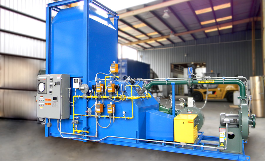
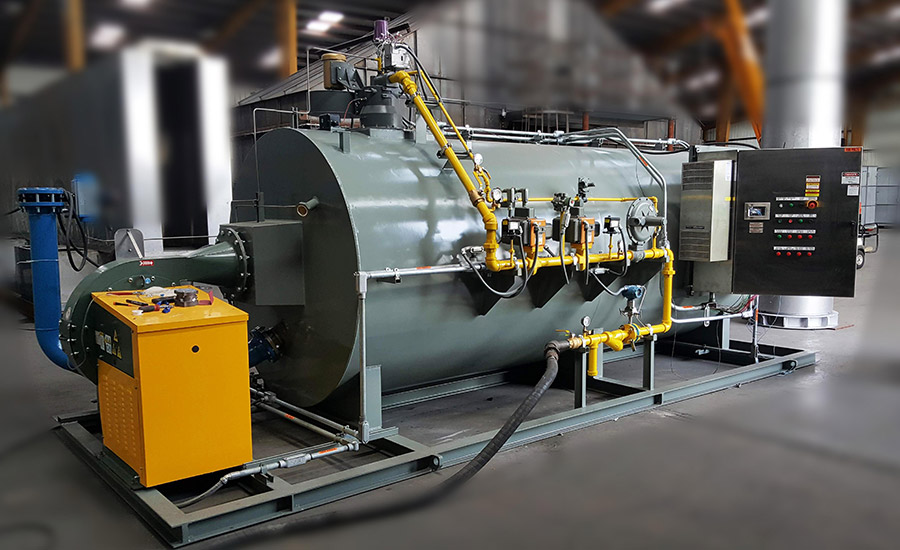
Epcon had full turnkey responsibility for designing, manufacturing, and commissioning the system on the job site to be sure the equipment exceeded all requirements once in operation. The new DFTO, waste heat boiler, and secondary heat recovery system destroy the complex VOCs in the tape manufacturer’s process, allowing the facility to keep operating in compliance and well above regulatory standards. The new integrated system has eliminated almost all the operating fuel cost previously needed for the air pollution control system. In addition, the new equipment does not require costly maintenance and downtime.
While regulations have been driving much of the demand for air pollution control, attention is increasing for the added environmental benefits of having well-designed equipment. For example, if a traditional RTO had been supplied for this application, thousands of pounds of polluted and toxic ceramic fiber media would need to be removed, thrown out, and ultimately end up polluting landfills.
As industrial manufacturers embrace their roles as environmental stewards, their focus extends beyond the scope of their immediate operational demands and instead shifts toward the lasting environmental impacts of their operations and processes. Across industries and applications, more manufacturers are taking the extra time and even upfront equipment costs to make the “greener” choice—not just for long-term economic goals but also for their environmental bottom line.
For more information, visit https://epconlp.com.
Note: Images courtesy of Epcon Industrial Systems.
Looking for a reprint of this article?
From high-res PDFs to custom plaques, order your copy today!


