Progressive Cavity Pumps in Meter-Mix-Dispense Systems
Incorporating a progressive cavity pump helps minimize product waste while providing operational efficiencies in meter-mix-dispense systems.

Meter-mix-dispense systems are designed to dispense single- or multi-part fluids with the exact volumetric ratio specified by users or manufacturers. These systems can be developed step by step through an understanding of the fluid properties and the basics of the existing technologies. Every detail, such as the fluid chemistry, viscosity, specific gravity, filler existence, filler amount, mixing ratio, flow rate, and container size, is critical in specifying and building a robust meter-mix-dispense system.
These systems provide an alternative to manual mixing and application. With manual mixing, end users may face problems like under- or over-producing, leading to unused waste product. Although it is possible to achieve accurate mixing and metering with a manual process, it does not guarantee high-quality, uniform, and accurate ratio mixtures.
Compared to manual processes, manufacturers using meter-mix-dispense systems save time, increase accuracy, and decrease costs associated with labor and adhesive loss. Meter-mix-dispensing equipment can be customized based on the material needs and application requirements.
Basics of Meter-Mix-Dispense Systems
Two-part adhesives, such as epoxies, silicones, polyurethanes, and acrylics, are often used in manufacturing environments where the need to bond, protect, and secure is essential. To meet these needs, meter-mix-dispense systems are used heavily in applications such as automotive batteries and electronics.
Two-component products are provided as a base component (A) and a hardener component (B). When these two components are mixed, a chain reaction occurs that initiates the curing process. The reaction generally lasts from a few seconds to a few hours, but it can also take a few days for the adhesive to achieve its final cured state.
Two-part meter-mix systems meter the amount of A and B materials to achieve the right ratio. These materials are often combined through a static mixer, which blends the parts into a consistent mixture. Most meter-mix-dispensing systems include a controller with a feature that recognizes the length of time material has been stagnant within static mixers. The system controller takes the necessary steps to ensure that changes in viscosity and shorter work life are not detrimental to the defined process by initiating a purge sequence to introduce fresh material to the static mixer.
In general, essential components of a meter-mix-dispense system are the feed system (pumps/reservoirs/cartridges), the meter, and the dispense valve. For high-viscosity materials, dispensing equipment is usually configured with piston/rod displacement pumps or sometimes gear pumps for feeding the material, while lower viscosities can be moved using pressurized reservoirs.
Once under pressure by the feed pump or reservoir, the material(s) are run to the meter and from there to the dispensing valve. Progressive cavity (PC) pumps eliminate the need for a dispense valve, however, as metering is done at the point of dispense.
Role of Progressive Cavity Pumps
The PC pump is a positive displacement pump that facilitates accurate feeding of medium- to high-viscosity materials such as thermal pastes or gels. It ensures minimal waste of material, reducing the environmental impact of the manufacturing process. PC pumps also provide many operational advantages, including continuous flow (doesn’t require reload), constant volume at variable speeds, no pulsation, and low maintenance.
PC pumps operate through the interaction of a stator and rotor assembly, which work together in an interference fit to make non-vibrating movement and precise metered displacement (see Figure 1). As the rotor revolves inside the stator, the material is continuously transferred through a sequence of cavities within the pump. Since the cross-sectional area of cavity is always constant regardless of the rotor position, dispensing volume remains consistent. In addition, both the per-unit time and overall volume are directly proportionate to the speed of rotor rotation.
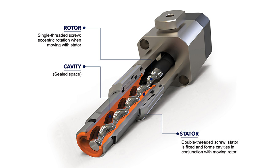
Figure 1. Progressive cavity pumps operate through the interaction of a stator and rotor assembly. As the rotor revolves inside the stator, the material is continuously transferred through a sequence of cavities within the pump.
This continuous flow pushes the material rather than squeezing or shearing. Because of this relatively gentle pushing motion, PC pumps can be used for pumping a variety of materials, including those that are filled with sensitive or abrasive materials. A gear pump is not recommended for these materials; sensitive fillers would be damaged by the actions of a gear pump, while abrasive fillers would damage the gears.
Standard rotors are stainless steel in PC pumps. If a particularly abrasive filler needs to be dispensed, such as those found in some thermally conductive pastes, tungsten carbide rotors are available to ensure the long-term endurance of the system. Progressive cavity pumps are available in different sizes to meet a range of applications, as well as in a variety of dimensions, weights, max dosing pressures, dosing volumes, and motor speeds.
When integrated with a gantry robot or multi-axis automation line,* PC pumps can provide precise and efficient dispensing in exact locations and repeatable programmed patterns. This solution can dispense highly accurate, reliable flow for a variety of single- or multi-component materials.
Tailored Solutions
By considering the specific fluid properties and available dispensing technologies, meter-mix-dispense systems can be developed to support various material characteristics, from fluid chemistry, viscosity, filler existence, and mixing ratio (all found on the material safety data sheet), to flow rate and environmental conditions. For many applications, incorporating a progressive cavity pump helps minimize product waste while providing operational efficiencies. Before beginning a project, it is best to bring in a dispensing expert to analyze the requirements and recommend the ideal key components for the application.
For more information, visit www.hernon.com.
*Such as Hernon’s Autobonder® three- or four-axis automation line
Note: Images courtesy of Hernon Manufacturing Inc.
Looking for a reprint of this article?
From high-res PDFs to custom plaques, order your copy today!


