Fiber Glass-Reinforced Polycarbonate Compounds

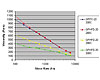
Figure 1. Viscosity vs. Shear Rate for GFPC-20 and GFHFD-20
It has been documented that the addition of short-fiber glass to polycarbonate materials results in an increase in modulus, improved dimensional stability and enhanced flame resistance.2-4 However, several disadvantages are involved when adding fiber glass to polycarbonate materials, particularly loss of transparency, decrease in ductility and toughness, and increase in melt viscosity. Numerous studies have focused on investigating the affect of glass fiber surface coating, fiber aspect ratio, and fiber orientation on the mechanical properties of thermoplastic compositions.5-7
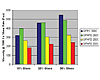
Figure 2. Viscosity at 1500 s-1 for GFPC and GFHFD
Some demonstrated advantages of the HFD copolymer resins compared to standard BPA polycarbonate include improved molding capability for long flow-length or thin-wall parts, lower temperature processing capability, improved low-temperature ductility, and superior mold release performance. In addition, preliminary studies have shown that fiber glass-filled formulations of HFD copolymers result in improved visual appearance and higher surface gloss in injection molded parts.14
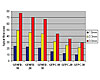
Figure 3. Spiral Flow Molding for GFPC and GFHFD (Tmelt310°C, Tmold85°C)
Study Specifics
A study was undertaken to examine the physical and mechanical properties of fiber glass-filled HFD copolymer compositions at 10, 20, and 30% glass loadings, and to compare the performance of these materials to comparable glass-filled standard polycarbonate products. The comparison covers typical ASTM testing parameters such as melt flow rate (MFR), heat deflection temperature (HDT), izod and multi-axial impact, as well as tensile and flexural modulus. In addition, the melt viscosity and spiral flow molding performance of the glass-filled HFD and standard PC materials are presented.Injection molding studies using a polished square plaque tool were performed in order to evaluate the effect of resin melt temperature, mold temperature, and injection speed on surface gloss for the glass-filled HFD and PC materials. Finally, the influence of melt viscosity, as well as formulation heat deflection temperature on molded plaque surface gloss, was evaluated by screening a range of HFD copolymer compositions with varying HDT and melt viscosity rate (MVR) properties.
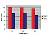
Figure 4. Molded Plaque Surface Gloss (Tmelt320°C, Tmold115°C)
All formulations were thoroughly compounded in a 30 mm co-rotating twin screw (Werner & Pfleiderer, ZSK-30) extruder using a melt temperature of 300°C with a rate of 20 kgs/hr, 20 in. of mercury vacuum and a screw speed of 400 rpm. Chopped fiber glass was added during the compounding step via a downstream feeder. The extrudate was cooled under water, pelletized and dried at 120°C for four hours with a desiccant bed dryer.
To make test specimens, the dried pellets were injection molded using a Van Dorn 80T molding machine at 300°C melt temperature to form test parts for impact and mechanical testing. Physical and mechanical properties of the test materials in this study were measured using ASTM and ISO test standards. Viscosity vs. shear rate measurements were performed using a Kayeness capillary rheometer. Spiral flow molding studies were performed at a melt temperature of 310°C; mold temperature of 95°C; and channel depths of 1.5, 2.3, and 3.0 mm. The surface gloss for glass fiber-filled PC and HFD samples was measured on 100 mm square plaques at 2.5 mm thickness; 60° gloss measurements were recorded using a BYK Microgloss gloss meter.

Results and Discussion
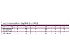
The physical and mechanical properties of fiber glass-filled HFD copolymer and standard PC materials were screened using a battery of standard ASTM and ISO test methods. The results of this comparative study are listed in Table 1.The HFD copolymer samples show significantly higher MFR and MVR compared to the standard polycarbonate examples for 10, 20 and 30 wt % glass loadings. The increase in melt flow between HFD and standard PC materials becomes larger as glass content increases. For example, GFHFD-10 shows 2.5 times higher MVR compared to GFPC-10. However, GFHFD-30 shows four times higher MVR compared to GFPC-30. (The relative differences in melt viscosity between the glass-filled HFD and PC materials will be further evaluated using capillary rheology and spiral flow molding in upcoming sections.)
As was previously reported for unfilled HFD copolymer resins, the glass-filled HFD samples consistently show lower HDT values compared to the glass-filled standard PC materials.14 As is expected with fiber glass-filled systems, the glass-filled HFD and PC materials show roughly 5-10°C higher HDT values compared to their unfilled counterparts. The difference in HDT between GFPC and GFHFD examples increases with increasing fiber glass content; at 10% glass the delta is 11-12°C, whereas at 30% glass content the difference is 17-18°C.
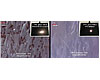
Figure 5. 50x Optical Microscopy of Plaque Surface for GFPC-10 and GFHFD-10
The GFPC-10 and GFPC-20 samples show 10-20% higher instrumented impact energies compared to GFHFD-10 and GFHFD-20, while GFPC-30 and GFHFD-30 materials displayed nearly equivalent performance. It is important to note that the GFPC-10 and GFHFD-10 samples both showed 100% ductility in the 23°C instrumented impact testing, whereas the 20 and 30% glass PC and HFD samples all showed 0% ductility.
A comparison of the mechanical properties of glass-filled polycarbonate and glass-filled HFD copolymer materials shows very similar flexural and tensile modulus values. As expected, the modulus or stiffness of these materials increases with increasing fiber glass content. Tensile strength results were also nearly identical between the GFPC and GFHFD samples. These results indicate that there are no significant differences in resin-glass adhesion, and no significant differences occur in glass attrition during processing between the HFD copolymer and standard PC materials. Density, mold shrinkage performance, and thermal expansion properties were nearly identical between the PC and HFD samples across the 10-30% fiber glass content range.
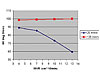
Figure 6. Surface Gloss vs. MVR for GFHFD-20 Compositions (Tmelt320°C, Tmold115°C)
In order to further examine the differences in melt viscosity between the GFPC and GFHFD materials, a capillary rheometer was used to measure viscosity over a range of shear rates and melt temperatures. The results of this analysis for 20% glass-filled PC and HFD samples are shown in Figure 1. In the shear rate range that is most typical of injection molding processes (in general, between 1000-5000 s-1), the GFHFD-20 material shows around 50% lower melt viscosity compared to GFPC-20 at 300°C melt temperature. The viscosity vs. shear rate curve for GFHFD-20 at 260°C overlaps almost perfectly with the curve for GFPC-20 at 300°C. From a practical perspective, this data indicates that in an injection molding application the GFHFD-20 material should process similar to the GFPC-20 sample, but at around a 40°C lower melt temperature. Molding at lower melt temperatures can have several advantages, including lower energy costs, reduced degradation of the polymer matrix, and reduced visual defects such as mold deposits or splay.
The capillary melt viscosity at a constant shear rate of 1500 s-1 for 10, 20, and 30% glass-filled HFD and PC materials is shown in Figure 2. At a melt temperature of 300°C, the glass-filled HFD materials show 40-65% lower melt viscosity compared to the GFPC samples. As is expected based on the MFR and MVR data, the difference in melt viscosity between HFD and PC materials is larger at higher glass content.
Spiral flow molding is a tool often used to compare the practical flow length of materials under similar processing conditions. The spiral flow tool used in this study has a fixed channel width of 16 mm and a channel depth that can be varied from 1.5-3.0 mm. The results of spiral flow molding at a melt temperature of 310°C and a mold temperature of 85°C are shown in Figure 3.
Based on this data, the GFHFD materials show 50-130% longer flow lengths compared to their GFPC counterparts at similar fiber glass loading. The magnitude of increased flow length for GFHFD vs. GFPC increases with increasing glass content. It is possible to make an estimate of potential part thickness reduction by measuring spiral flow molding over a range of channel depths and comparing the GFHFD and GFPC materials at a given spiral flow. For example, the spiral flow value of GFHFD-20 at ~ 2 mm thickness is equal to the spiral flow of GFPC-20 at 3.0 mm, which corresponds to a roughly 33% reduction in part thickness.

Figure 7. Surface Gloss vs. HDT for GFHFD-20 Compositions (Tmelt320°C, Tmold115°C, inject speed 75 mm/s)
It has been previously documented that fiber glass-filled compositions of HFD polycarbonate copolymer show higher surface gloss in injection molded plaques compared to comparable glass-filled standard polycarbonate materials.10,14 An example of this is shown in Figure 4, where, under a given set of molding conditions, the GFHFD materials show 30-50% higher 60° gloss compared to the GFPC samples. When the surfaces of the plaques generated in this study are analyzed by optical microscopy, it is clear that the reduction in gloss for glass-filled materials (compared to an unfilled sample) is caused by exposed glass fibers at the part surface (see Figure 5). In the case of the GFHFD-10 example, the glass fibers are buried underneath a thin layer of resin, resulting in higher gloss and overall improved surface aesthetics.
An injection molding study was completed using a polished-surface square plaque tool to illustrate the effects of melt temperature, mold temperature, and molding injection speed on surface gloss. The results of this study, which compares results for the 20% glass-filled GFHFD and GFPC materials, are shown in Table 2. From the data, it is clear that increasing resin melt temperature, increasing mold temperature, and increasing injection speed all result in an increase in surface gloss.
In all cases, the GFHFD-20 material showed higher surface gloss than the GFPC-20 samples. The ability to achieve higher surface gloss is particularly important for parts requiring a good aesthetic appearance or applications where multiple coats of paint are normally required to hide any exposed glass fibers. In addition, certain part geometries or designs do not allow for extremely high melt or mold temperatures to achieve a high surface gloss. The glass-filled HFD materials therefore offer a broader processing window to achieve a higher gloss finish compared to a standard glass-filled PC.
As stated previously, the two major physical property differences between the GFPC and GFHFD compositions are melt flow and HDT. It is conceivable that either or both properties could contribute to producing higher gloss surface appearance for the GFHFD materials.
In order to isolate and evaluate these properties, two separate experiments were performed. In the first experiment, a range of 20% glass-filled HFD compositions was compounded at the same HDT target (130°C at 0.45 MPa), but with varying melt flow targets. The results of injection molding studies with these materials are shown in Figure 6. Based on the gloss data at slower injection speeds (25 mm/s), it is evident that surface gloss decreases with decreasing melt viscosity (increasing MVR).
However, it was noted during these experiments that, as MVR increases, the pressure inside the mold decreases accordingly. When the injection speed was raised (125 mm/s), a consistently high surface gloss was observed across the entire MVR range. These results indicate that the in-mold pressure, which is a function of both resin melt viscosity as well as injection molding speed, is a key contributor to achieving higher surface gloss. A material with a higher MVR, such as the glass-filled HFD compositions, allows for larger/thinner wall parts and faster injection speeds, which can potentially improve molding cycle time and productivity.
In the second set of experiments, a range of 20% glass-filled HFD copolymer compositions were compounded at the same MVR target (11 cm3/10 min at 300°C/1.2 kg) but with varying HDT targets. Injection molding studies on these materials at a fixed set of process conditions resulted in a clear trend, showing decreasing surface gloss with increasing formulation HDT (see Figure 7).
From these results, it is clear that, at a given processing condition, the GFHFD materials with lower HDT remain in a molten state for a longer time during injection molding, which allows the resin to flow around the glass fibers and yield a more resin-rich surface. Therefore, the combination of lower HDT and higher melt flow (ability to mold at faster injection speeds) enables the glass-filled HFD copolymer compositions to yield a higher gloss surface compared to an equivalent glass-filled standard polycarbonate material.
Conclusion
In summary, the fiber glass-filled HFD polycarbonate copolymer materials are characterized by significantly higher melt flow compared to their equivalent glass-filled standard polycarbonate samples. The GFHFD compounds show 11-18°C lower HDT compared to the GFPC products, but have relatively similar impact, mechanical, and dimensional stability properties.The glass-filled HFD copolymer materials allow for longer practical injection molding flow lengths and part thickness reduction. In addition, the glass-filled HFD samples yield improved surface gloss in injection molded plaques compared to the standard glass-filled PC materials.
In general, increasing resin melt temperature, mold temperature, and injection speed results in an increase in surface gloss and improved aesthetic appearance. Due to their higher flow and lower HDT properties, the glass-filled HFD copolymer materials offer a broader injection molding process window to achieve a higher gloss surface.
For more information, contact SABIC Innovative Plastics at One Plastics Ave., Pittsfield, MA 01201; call (413) 448-7110; or visit the website at www.sabic-ip.com.
Author's Notes
The author would like to acknowledge Don Wedding and Mike Oeth for their work in formulating/compounding the test materials and performing the injection molding studies. Figures and tables are provided for general information only and are not for the purpose of warranty or specification. In all applications, testing of a part in end use conditions is strongly recommended.References
1. LeGrand, D. G., Bendler, J. T., Handbook of Polycarbonate Science and Technology, 2000, Marcel Dekker, Inc., New York.2. Schweizer, R. A., Winterman, A. W., Thermoplastic Polymer Additives, 1989, Marcel Dekker, Inc., New York.
3. Ramsteiner, F., Theysohn, R., Composites Sci. and Tech., 1985, 24, 231-240.
4. Gallucci, R. R, “Short Fiber Glass Reinforcement of Ductile Resins,” ANTEC 2004.
5. Parkar, A., Nunn, R. E., Orroth, S. A., “Fiber Length Degradation in the Feed Zone During Injection Molding,” ANTEC, 1994.
6. Wolf, H. J., Kunstoffe, 1993, 83, 69-72.
7. Gemmell, L. M., Tennant, O. W., Gallucci, R. R., U.S. Patent 5,384,353.
8. Goldberg, E. P., U.S. Patent 3,169,121.
9. Fontana, L. P., Buckley, P. W., U.S. Patent 5,025,081.
10. Fontana, L. P., Morioka, M., U.S. Patent 5,106,904.
11. Fontana, L. P., Reed, R. A., U.S. Patent 5,455,323.
12. Hoover, J. F., Fontana, L. P., U.S. Patent 5,608,026.
13. Dan, W. H., Patterson, D. J., Boutni, O. M., Fontana, L. P., U.S. Patent 5,777,009.
14. Malinoski, J. M, “Physical and Mechanical Properties of New High-Flow Polycarbonate Copolymers,” ANTEC, 2010.
Links
Looking for a reprint of this article?
From high-res PDFs to custom plaques, order your copy today!


