Understanding Net Weight Filler Configuration and Performance
Gravimetric or net weight fillers have replaced other fill methods in the CASE industry due to their ease of automation, flexibility, and accuracy.

Automatic fillers are used to achieve faster container rates and reduced operator intervention. This four-head automatic filler features a lateral transfer conveyor, cone nozzles, and a DFS fill cart.
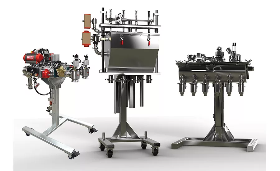
Manifold fill systems (left) consist of a main supply and branch lines that split the flow to each individual fill head. Direct fill systems (center) include a reservoir and a single product delivery valve, and pressure over product systems use a closed, pressurized reservoir to control product flow across multiple filling heads.
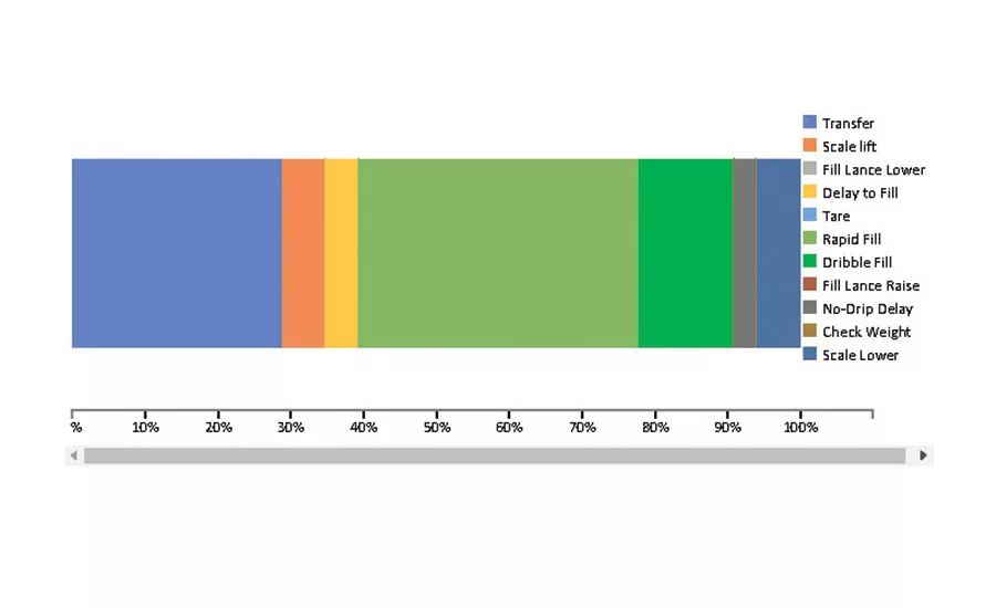
Figure 1. A filler performance tool calculates fill rates in gallons per minute and containers per minute, as well as the percentage of time spent in filling and non-filling operations.
While many filling technologies exist, gravimetric or net weight fillers remain a predominant fill method in the CASE industry. These fillers utilize a scale to measure the precise amount of product dispensed to a container. They have replaced other fill methods due to their ease of automation, flexibility to handle multiple container sizes and varying product densities, and ability to maintain accuracy even with products containing entrapped air.
Net weight fillers are supplied in both automatic and semi-automatic configurations. Semi-automatic fillers feature one or two fill heads. During semi-automatic operation, the operator places containers under each fill head. A button is pressed to initiate fill, and fill stops when the targeted weight is reached. The operator removes the filled containers, and the process begins again.
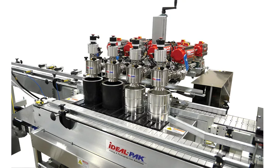
Automatic fillers are used to achieve faster container rates and reduced operator intervention. Available in one-, two-, three-, four-, six, and eight-head configurations, automatic fillers index containers under the fill heads from an upstream queue. The fill cycle starts and stops automatically, and new containers move under the fill heads as full containers proceed downstream.
Filling Process
Several factors affect container fill rates and accuracy. A slower fill rate produces more accurate container filling. However, a higher flow rate is desirable for faster throughput. Since valve response is not instantaneous and product is in freefall, which is outside the readings of the scale, flow is stopped before the target weight is reached. A preact weight is therefore determined to account for material entering the container after the valves are signaled to close.
Three set points are controlled during the filling process: target weight, dribble weight, and preact. Valve operation occurs without operator intervention for both automatic and semi-automatic container filling. The fill cycle begins at rapid fill and then switches to dribble. When preact is reached, the valve close is initiated. Once all flow stops, the container reaches its target weight.
For example, consider a target weight of 9 lbs, dribble weight of 1 lb, and preact of 0.2 lb. Following fast fill to 8 lbs, the filler switches to dribble. Valve close is then initiated when the weight reaches 8.8 lbs.
Nozzle Selection
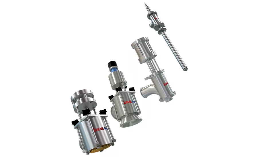
Nozzles are an important part of liquid filling machines. Product characteristics and container types and sizes dictate the best nozzle choices. The four main nozzle types include shower head, cone nozzle, plug nozzle, and fill lance.
When filling large open-top containers, the vented cone nozzle is an ideal choice because it operates over a large viscosity range. As product flows past the cone, it forms a 360˚ curtain, rather than a solid stream. This curtain reduces the likelihood of foaming and splashing. The central vent allows air to escape from the center of the curtain as the liquid level rises. On closing, the cone nozzle produces a sharp cut of material flow, eliminating the dripping and stringing that may be present with other nozzles.
For low- to medium-viscosity products, the shower head nozzle allows for rapid drip-free filling. The shower head features a plate with a series of precision holes. Material flows in a small stream from these holes, reducing the likelihood of splashing. When flow is stopped, capillary action prevents further dripping. Interchangeable plates allow the nozzle to be tailored to a specific product. The shower head nozzle can be supplied in sizes to accommodate ½-pint through 6-gal open-top containers. It is ideal for filling light coatings, solvents, and stains.
Small container openings or high viscosities lend themselves to a plug nozzle. Material exits the plug nozzle in a solid stream. In many applications, the nozzle extends inside the container to eliminate splashing as the solid stream contacts the liquid surface. This type of nozzle is ideal for high-viscosity products, as it provides the least restrictive path for the product to travel and enables higher fill speeds and less backpressure.
When foaming or static is at issue, the lance/probe nozzle is used. The probe nozzle is designed for bottom-up filling. During the fill, the fill lance is extended to the bottom of the container, reducing product free-fall and eliminating foaming. The nozzle is retracted as the liquid level in the container rises. Since the product is typically discharged under the liquid surface, the nozzle will be coated in the product. A drip cup is normally employed to catch material dripping from the nozzle and can direct the material back to subsequent containers.
Product Delivery
Product delivery to the filler needs to be split equally to all fill heads. The most common delivery method is manifold fill, which consists of a main supply and branch lines that split the flow to each individual fill head. As the nozzles will not seal against the pressures from the supply pump, each branch includes three valves and the nozzle. The shut-off valve controls flow to the fill head. This two-position valve is either open to fill or closed to stop the flow. The dribble valve is also a two-position valve. In the open position, the dribble valve allows for the rapid fill cycle. The second position is only partially closed. This position restricts flow for the dribble cycle and is adjustable to vary flow rates and to control the accuracy of the filler. The third valve is a balancing valve, which is typically a manual valve adjusted to ensure equal product delivery rates to each fill head. During startup, each dribble and balance valve is adjusted to tune the flow to each of the fill heads.
The direct fill system (DFS) consists of a reservoir and a single product delivery valve. The valve is cycled to maintain a consistent level in the reservoir. Nozzles are incorporated directly to the bottom of the reservoir. The DFS uses head pressure to deliver a consistent flow to each of the fill heads. It is applicable for low- to mid-range viscosities. The reservoir level can be adjusted to vary flow rates from the heads to impact fill speed and control splatter. Balancing and dribble for each head is adjusted directly at the nozzle. Nozzles effectively seal against the head pressure in the reservoir. With flow control, dribble, and balance handled, the need for branch valves is eliminated. Consistent flow from the constant head pressure allows top filling of many foamy products. It also eliminates the need for consistent product supply flows. With fewer valves (one valve vs. three per nozzle), the DFS allows for easier cleanup and reduced maintenance.
The pressure over product (POP) system has many of the same advantages as the direct fill system, including a single product delivery valve and adjustments for flow, balance, and dribble at the nozzles. Instead of head pressure, the POP uses a closed, pressurized reservoir to control product flow across multiple filling heads. Higher pressure delivery extends the effective viscosity range. The external nozzles introduce additional cleaning requirements but offer easier changeout and flexibility.
Product Supply
While typically not part of the filler, product supply plays a critical role in the successful operation of a filler. Gravity, pumps, and hydraulic presses can deliver product to the filler. For DFS and POP delivery, consistent flow is not as important a concern. When supplying a manifold system, consistent flow is essential.
Gravity is by far the simplest means of supplying the filler. If the process tank is above the filler, gravity will deliver product to the filler, and flow can be controlled simply by closing a valve. The main drawback is that flow rates will change during the filling cycle as the level in the supply tank is reduced. This issue does not affect the DFS fillers since flow rates are set by the reservoir level and not feed pressure.
Air-operated double-diaphragm pumps (AODDs) are a simple and cost-effective means of supplying a filler. Surges from AODDs must be reduced when supplying a manifold system; a pulsation dampener should be installed in these cases. To function effectively, a valve must be installed immediately after the pulsation dampener to introduce backpressure. The supply can be dead-headed (valve can be closed against flow from the AODD), as the pumps will stall against the backpressure. However, the filler will also shut off air pressure to the pump to reduce backpressure and eliminate splatter when valves are opened. For DFS and POP systems, pulsation dampeners are not necessary.
Positive displacement pumps deliver a consistent flow to the filler. Unlike AODD pumps, positive displacement pumps cannot be dead-headed. The filler can toggle the pumps on and off, but this introduces a lot of wear and tear on the electric motors and introduces some safety issues. It is best to include a recirculation line. When flow to the filler stops, the pump can be stopped. Excess pressure is relieved as flow through the recirculation line, or the pump can continue to run, directing all flow through the recirculation line.
For products that do not free flow, a hydraulic ram press can be used. The press includes a platen that is fit to the inside diameter of the supply tank. Hydraulic pressure forces the platen down into the tank, pressing material out the discharge valve and to the filler. The press should include a variable displacement hydraulic unit, which allows the press to react to increased pressure during dribble and dead-head when the supply valve is shut.
Conveying Options
For in-line fillers, two main conveying options exist. For semi-automatic fillers and smaller automatic fillers, a single straight-through conveyor design is used. The single conveyor transports containers to and from the fill heads. For larger automatic lines like the six- and eight-head fillers, as well as some four-head fillers, the time to convey the first container past all the fill heads to the last position may become excessive.
A lateral transfer conveyor is used to decrease conveyor time for larger automatic lines. The lateral transfer conveyor consists of two parallel conveyors with the fill heads in between. Containers are staged on the in-feed conveyor behind each fill head. Once full, all containers are moved in a single transfer to the discharge conveyor. At the same time, the staged conveyors are moved under the fill heads, ready for the next cycle.
A variable-speed conveyor allows line speeds to be adjusted to avoid material “sloshing” out of the container when accelerating from full stop under the fill head to line speed. This is especially critical for open-top containers with low-viscosity materials and high fill levels, though sloshing can occur in any container and any material.
Filler Performance
The main questions usually asked about a filling line involve fill rate and containers per minute—in other words, speed. While it appears a straightforward question, many variables impact the fill rate. The most obvious variables have been discussed here previously. Proper nozzle selection allows splash-free filling at high rates. Further improvements can be achieved by establishing a dribble weight to a minimum level that still consistently delivers the desired accuracy. Increasing the conveyor speed also improves filler throughput.
For these variables, product viscosity plays a major role. A thin product may splash or foam and, if filled close to the top of a container, can spill as the container leaves the filling area. A slightly more viscous product may allow for quicker filling and transport. That is why it is important to understand the product viscosities, container sizes, container types, and fill levels.
Even once these times are set, many additional time-consuming operations occur during the filling cycle. While these operations may only represent a fraction of a second each, they can have a large impact on performance. Some of these delays are optional, while others are required to perform a physical task.
For automatic machines, it is important to isolate the container from vibrations caused by the moving conveyor. Typically, the scale is lifted, raising the container off the moving conveyor. At the end of the fill cycle, the scale must be lowered to allow the container to be conveyed from the fill zone. In the case of sub-surface filling, time is consumed for the lance to travel to the bottom of the empty container and to be removed from the filled container.
Pre-fill, it might be necessary to test that a container is in place before opening the fill nozzle. To do this, a slight delay is imposed to allow the scale to settle and ensure a minimum weight is present on the scale to account for the container. It might also be desirable to get a more accurate tare weight for record-keeping purposes. Post-fill, delays might be added to allow the last of the product to drip from the nozzle or to get a final check-weight. Together with conveying, these non-filling operations can account for 40-70% of the total fill time.
A tool can be used that demonstrates the effects of operational timing, including supply rates, dribble settings, conveyor configurations, and speeds and delay settings (see Figure 1). In response to selections, the tool calculates fill rates in gallons per minute and containers per minute, as well as the percentage of time spent in filling and non-filling operations. With a solid understanding of product characteristics, container types and sizes, accuracy needs, and documentation and traceability requirements, filler manufacturers can assist in specifying the filler that best suits specific needs.
For more information, contact the author at (610) 668-9500 or steve@dispersetech.com, or visit www.dispersetech.com.
Looking for a reprint of this article?
From high-res PDFs to custom plaques, order your copy today!


