Process Design Decisions for Successful Form-in-Place Gasket Sealing
Innovations in automotive design have led to substantial changes in how form-in-place gaskets (FIPGs) are used today.
Form-in-place gasket (FIPG) sealants are well-established in the automotive sector for seal applications such as oil pans, drive trains, and cooling systems. However, innovations in automotive design have led to substantial changes in how FIPGs are used today. Heuristics established for previous generations of designs and materials are no longer applicable.
Joint Design
Liquid gasket design is simpler than solid gasket design because liquid gaskets are more forgiving, but essential design considerations must still be employed to achieve good sealing. The geometry of the flange is critical to how the sealant will perform. It is important to consider the balance of metal contact width, as well as the FIPG’s thickness volume, initial hardenability, and elongation rates (see Figure 1).
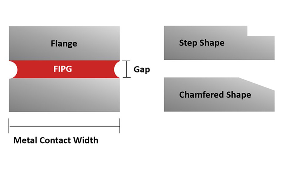
Figure 1. Flange geometry is critical in how the sealant will perform.
The most common mistake in liquid gasket design is failing to design a proper flange for the sealant. Tiny flanges do not allow the sealant bead to have sufficient thickness for a robust seal. When you put the sealant on a tightrope, there is much more scope for the development of leak paths.
Increasing the metal contact width also increases initial pressure resistance, which is important because many manufacturing processes include an in-line pressure test to evaluate the sealing capability of partially cured FIPG material. Excessive pressure applied to partially cured material will damage the seal, but a wider metal contact width will better protect the FIPG while it cures.
The FIPG thickness volume is controlled by the gap size and metal contact width. Increasing the FIPG thickness volume increases sealability under vibration. More sealant volume means more ability to stretch before breaking but reduces both initial pressure resistance and sealant strength.
Chamfer and step flange designs are used to provide better initial sealing and a thicker bead to allow movement in the flange. Flange chamfer width and angle must be set by considering the balance of initial pressure resistance and compliance with movement. It is important to avoid groove designs because they have poor moisture migration into the bulk, causing them to cure slowly. Additionally, grooves provide less ability for the sealant to deform and comply with the substrate to achieve a good seal. In general, wider flanges are better for sealing, and small gaps are better for initial testing.
Properly designing and supporting the joint is becoming increasingly important with the trend toward making cars out of plastics, lightweight composites, and thin sheets of stamped metal. These newer materials tend to have a lot of flex, which means that joints are exposed to twists, tension, compression, shear stresses, and other movements.
FIPGs were originally designed for bolted metal joints. Accordingly, the low strength of traditional FIPGs was not a problem because they could function solely as sealants without taking on a structural role. Any displacement in the joint assembly or operation will compromise the seal.
Mechanical fastener spacing and location are crucial for stabilizing joints. The maximum acceptable spacing between mechanical fasteners depends on the flexibility of the joint materials, as well as the width of the flange. Positioning a mechanical fastener at each corner is the most secure design, but other considerations often lead the designer to prefer to position the fastener along the side near the corner instead. Even if the fastener spacing is sufficient, however, a non-corner fastener placement can allow a corner leak path because of the way stresses propagate along the design.
It is also important to avoid high-pressure ports. Surround these locations with a press-in-place or edge-bonded carrier gasket, with a room-temperature vulcanizing (RTV) silicone-based FIPG as the secondary sealant using concentric or semi-circular grooves.
Another concern with the new generation of vehicular materials is the coefficient of thermal expansion (CTE). CTE mismatch and creep with plastic substrates can pop joints, so any joints subject to temperature changes may require stiffening structures.
The new materials require a fresh focus on surface properties as well. Many new-generation materials have low surface energy, which makes them difficult to bond, so it is necessary to optimize the bonding conditions for each material depending on the specific surface chemistries.
These materials may initially have a surface energy of about 30 dynes but can be treated to increase the surface energy to 40-60 dynes, which improves the ability of sealants to wet onto the surface and achieve a secure, leak-proof seal. The old roughness standard for FIPG substrates was 0.8-3 Ra, but a new roughness standard of 6-25 Rz should be established to better account for a variety of peak and valley shapes.
Substrate cleanliness also important. To achieve a good seal, the surfaces should not be greasy, dusty, wet, or have been washed in a basic solution (pH).
In addition to modeling, it is particularly important to investigate surface pressures on the actual part in the design stage. Modeling still cannot replace rigorous testing. It also is necessary to design for the product. Never use RTV sealant on a joint originally intended for another material unless the joint requirements for FIPG are satisfied in the joint design.
Selection Criteria
Since RTVs are silicone-based, they tend to have good overall chemical and temperature resistance properties. RTVs have been developed to perform better against specific chemicals such as engine oil, long-life coolant (LLC), automatic transmission fluid (ATF), differential oil, and others.*
It is important to identify any specific requirements when selecting an RTV for an FIPG. Most silicone RTVs have an operating temperature range of -40 to 250˚C. While this range covers most applications, RTV types that are resistant to higher temperatures are also available for high-heat applications.
Several design requirements are key when selecting the best RTV for an FIPG application. It is important to determine the requirements for the project and share this information with the RTV supplier:
- Viscosity/sag
- Skin over time
- Time to full cure
- Adhesive strength to various surfaces
- Color
- Outgas (electronics)
- Elongation
- Compatibility with substrate (not promote corrosion)
- Thermal conductivity
- Flame resistance
- Compatibility with fluids
- Pressure resistance
Processing
All RTVs start as a liquid. When choosing to use this type of material for an FIPG, designing to the end result—a solid gasket—can cause problems. Since every manufacturing process has steps and takes time to fully assemble, this dwell time is key when using RTV.
The “liquid” sealant behaves as a “steady flow of viscous fluid between two parallel planes” when it is in the flange of components being mated. Even though the material is a liquid, it can still withstand pressures and maintain the seal. The viscosity of the material, the flange width, and the distance between the mating faces (gap) are key to a good seal until the material has cured thoroughly.
RTV cures by the reaction of humidity in the air. This reaction creates a polymer chain and continues until the material is fully cured. Most one-part, moisture-cure RTV cures at seven days, 55% relative humidity.
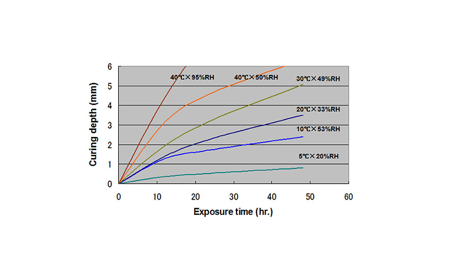
Figure 2. Effect of temperature and humidity on the curing of form-in-place gaskets. In general, FIPG cures about 2-3 mm at 20˚C and 50% humidity.
Curing happens from the outside to the inside. If you look at a flange, the “squeeze out” will start to cure and then work inward. If the humidity level is high, the cure speed will increase; if the humidity is lower, the cure rate will decrease. Typically, RTV cures faster in the warmer months and more slowly in the winter.
After applying the liquid gasket, assembly must take place quickly to ensure the material does not “skin” over, reducing the adhesion to the substrate. Dispensing the sealant onto a part and then allowing it to sit out too long, such as during a production break, can cause reduced adhesion and sealant failure.
In addition, the dispensing process must be designed to be completed before the sealant starts to skin over; this can be a challenge on a large part or a slow dispense. Timers and sensors need to ensure the parts are assembled quickly or not used if the recommended time is exceeded. Once the parts are assembled, they need to be fastened quickly to ensure the bond is not jeopardized if not completed.
When dealing with a solid gasket, the key to sealing is compression. A leak will occur when the mating parts are slightly out of spec. When using an RTV-based FIPG, the material can fill these voids and still provide great sealing performance. RTV does not use compression. Instead, seal integrity is determined by adhesion to the substrates and strength of the RTV.
Dispensing RTV Sealant
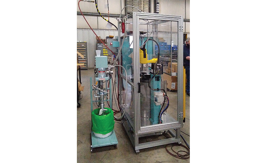
With today’s technology in robotics, dispensing RTV sealant can be an easy process. Depending on the RTV bead specifications, several options can ensure that the proper shape and size of the bead is applied to the flange. Dispensing systems typically include the following:
- Pump and hoses—move the sealant to the dispensing valve
- Regulators—maintain constant material pressure
- Dispensing valve—regulate material (pneumatic, servo, gear)
- Dispensing nozzle—control the size of the bead dispensed
- Robot—programmable; apply bead pattern onto the flange
- Machine base/part fixture—hold the part in place during RTV dispensing
- High-definition multimedia interface (HDMI)—control center for system
Due to design changes in the mating substrates, working with RTV and dispensing with a robotic system allows for easy adjustments of FIPGs. Instead of tooling change costs, longer lead times for changes, and possible manufacturing equipment costs, the program can simply be changed to adapt to the new design.
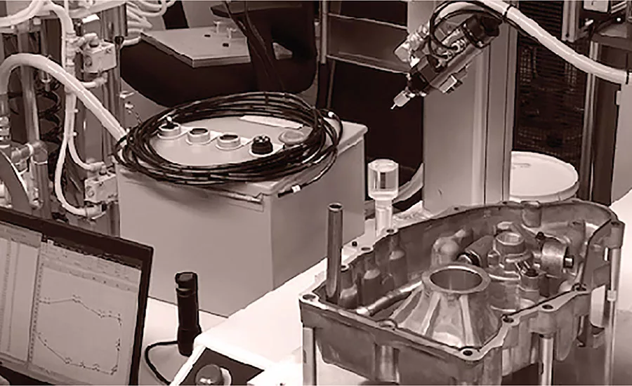
Automation enables easy and efficient sealant dispensing.
Sealing the Future
It has been over 40 years since RTV silicone was adopted widely by the automotive market, and numerous products and applications have evolved to meet the ever-changing market. While RTV silicone is a mainstay in the sealing of engines, the electric vehicle industry is adopting this technology for sealing battery enclosures and various access panels. As we move away from the combustible engine, RTV-based FIPGs playing a vital role in the future of the automotive market.
For more information, contact the author at tjones@threebond.com or visit https://threebond.com.
*Developed by ThreeBond International, Inc.
Note: Images courtesy of ThreeBond International, Inc.
Looking for a reprint of this article?
From high-res PDFs to custom plaques, order your copy today!


