Meter, Mix and Dispense Technologies for Two-Part Adhesives and Sealants
From early manual methods to fully automatic, microprocessor-controlled systems, the equipment has followed the trend toward:
- Increased productivity
- Minimized material contact with personnel
- Reduced environmental impact
- Reduced waste
- Safety
- Increased product reliability.
Processing urethane, epoxy, acrylic, silicone and other two-part systems requires very specific understanding of the adhesive-system formulation. This is a critical area of importance to the machine manufacturer. The adhesive system should be well defined, with a clear understanding of the formulation prior to machine design.
- Ratio weight/volume
- Specific gravity
- Filler type
- Corrosive
- Pot life
- Air content
- Viscosity
- Abrasive index
- Moisture sensitivity.
- Shot size
- Shot accuracy
- Shot frequency
- Heating
- Reservoirs
- Controls
- Vacuum degas
- Dryers
- Stationary/remote
- Data acquisition.
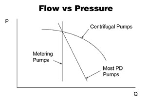
Rheology (material's reaction to an applied force) is an important aspect of system design. Generically referred to as viscosity, rheology describes how a material will flow in a system under pressure and possibly at elevated temperature.
Many adhesives and sealants exhibit non-Newtonian flow; the fluid does not behave in a consistent manner as shear stress (related to pressure in a metering system) changes. Some studies suggest that many materials are shear thinning in practice.
Pressure developed by the metering system drives the two fluids to the dispense point. With different rheology, the two fluids likely exhibit different flow characteristics. System-design considerations are focused on this disparity to prevent phasing (lead/lag) and other problems at the point of dispense.
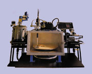
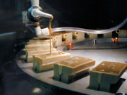
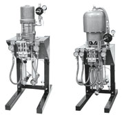
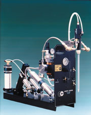
Fluids are not compressible, except in practice. Many adhesives and sealants are compressible to some degree due to the manufacturing method or additives in the material. In most positive-displacement systems, degassing the material prior to dispensing reduces compression. This is of particular importance where the dispense point is in vacuum. (See Figures 2 and 3.) By eliminating air, pressure in the metering cylinders has less effect on material compression, yielding more accurate metering.

Four Major Metering Methods
Piston
Four metering methods have evolved over the years; others exist to a lesser extent. Piston metering, both single-acting and double-acting, relies upon the movement of a piston a defined distance through a cylinder of fixed diameter. This method is quantifiable and repeatable. By adapting two piston/cylinder meters to a two-stream flow, precision metering and dispensing can be achieved.Several piston-metering variations exist: fixed-ratio (Figure 4, pg. S3) or variable ratio and single-acting or double-acting.
The variable-ratio system has adjustment for the stroke of one or both pistons. This allows ratio adjustment of the equipment without changing major components. (See Figure 5.)

The use of highly filled material with additives that may drop from suspension requires a single-acting system. Material may be dispensed through the head and the cylinders emptied, or the material may be returned to the reservoirs for agitation. (See Figure 7.)
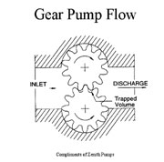
Gear
Gear metering provides unique operating characteristics due to the drive mechanism, typically electric or hydraulic. In either case, continuous speed adjustment throughout the operating range can be achieved. In applications such as robotic interface with changing-bead profile, the gear-metering system allows the system to finitely control the flow rate to the work. Data acquisition is made simpler, especially in the electrically driven system, as all functions are electronic. Shot size, shot rate, total material dispensed and other data can be fed directly to the plant supervisory system. All of this data is directly related to the rotation of the motor.Where applications such as molding require large pours, gear systems provide the continuous but variable-flow characteristics needed.
In the two-drive gear system, stepper motors independently drive each gear meter. By varying the individual speed of the stepper motor, ratio may be adjusted on the control console. This has advantages in applications such as Rapid Prototype Molding where different material systems and ratios may be used in the course of a day.
Practical considerations limit pump speed. High-viscosity materials may not fill the pump rapidly, creating starvation. Either the inlet pressure must be increased, the speed reduced, or both.
The gear meter relies on the metered fluid for lubrication of internal bearing surfaces, including the front and rear plates and the driven gear arbor. Accelerated wear and seizure of the pump will likely result from metering fluids of low lubricity or fluids with abrasive particles.
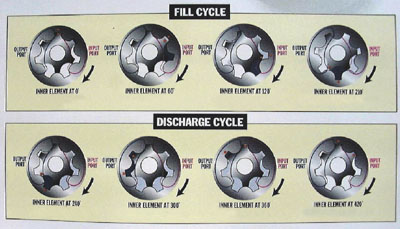
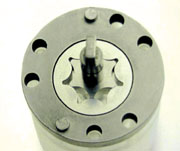
Geroter
Similar in operation but different in application to the gear meter is the Geroter. (See Figures 9 and 10.) The inner element has one less tooth than the outer element and has a centerline positioned at a fixed eccentricity from the centerline of the outer element. The displacement is a function of the inner and outer dimensions and the eccentricity between the elements.
These pumps provide accurate metering of thin to viscous materials at relatively low speed. As with the gear pumps, highly abrasive fluids could cause premature failure to the metering.
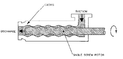
Progressive Cavity
The progressive cavity meter (Figure 11) is similar to an Archimedes screw. A single-screw, lobed rotor turns within a similarly shaped casing. As the spinning rotor fills with material, it is trapped by the outer casing and transported to the outlet and discharged. These types of meters may be constructed of various materials, including ceramic, which allows a wide range of processing capability, including abrasive materials. As with the gear meter, the progressive cavity may be independently driven by stepper motors, allowing ratio-range change through an electronic console.Conclusions
A wide overlap between metering type and applications exists. There are no clear guidelines as to which type of metering to use with a particular application. However there are limitations to some metering systems that do not exist in others.In general, many MM&D systems are on the market. The important aspects of choosing a system include the application knowledge of the companies under consideration, service capability (after-sales support), equipment durability and installed base. References should be freely available and ideally similar in nature to the project under consideration.
Click here for a PDF of our "2002 Guide to Dispensing and Curing Equipment."
Additional information on meter, mix, dispense equipment is available from Ashby Cross Co., 28 Parker St., Newburyport, MA 01950; call 978-463-0202; fax 978-463-0505; or visit www.ashbycross.com. Or Circle No. 73.
Links
Looking for a reprint of this article?
From high-res PDFs to custom plaques, order your copy today!


