Case Study
Making Automotive Sealers Behave
A cost-effective approach to extending the life of automobile bodies.
Prior to the 1980s, it was common for cars to rust. The lower doors and rocker panels were usually the first to go, followed by the floor pans, wheel wells and bumpers. Even the hood, deck lid and the roof were not immune. Aftermarket companies sprang up to “undercoat” cars to prevent rust. Automakers followed suit and offered undercoating as an option as they sought a solution.
Next came modern sealer technologies, which offered the opportunity to prevent corrosion in the places where it was most prevalent. This was far better than aftermarket solutions, which involved drilling holes and installing plugs after spraying. Sealers were incorporated into both the design and the manufacturing process. First applied manually, the sealers were an improvement, but still were unreliable.
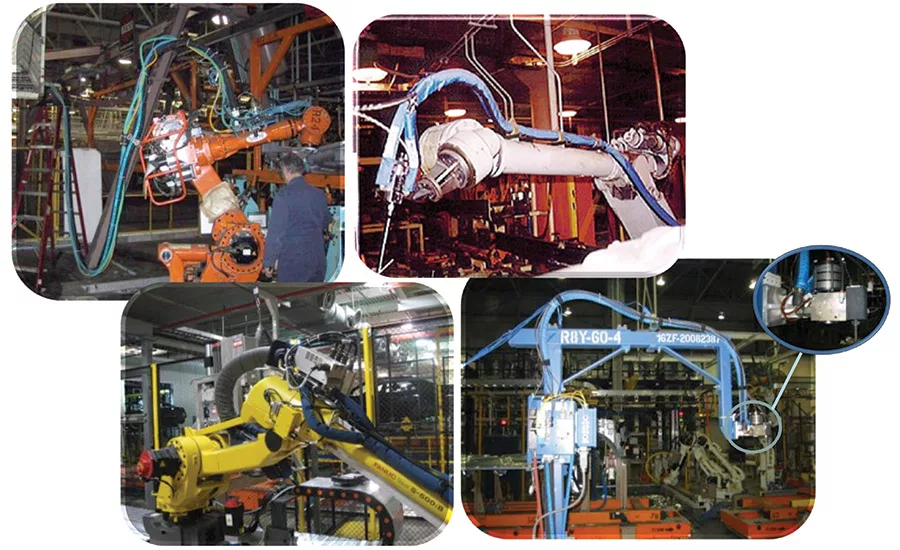
In the ’80s, robotics were just coming into their own, and they offered the opportunity to automate the repetitive, tedious, high-precision tasks of which humans quickly grow tired—including the application of sealer. But there was one major problem: hand-eye coordination. A human could watch the bead as it was being applied and change their speed, angle, distance to the part, etc., to create a good bead―something a robot wasn’t capable of doing. For a while, it seemed like robots weren’t cut out for this type of application. Then, in 1990, Saint Clair Systems (SCS) introduced new methods and devices for controlling the temperature of the sealer as it was dispensed, making the application viable. Today, robotically applied sealer is the norm throughout the industry, and virtually every successful system incorporates some form of temperature control to stabilize sealer viscosity (see Figure 1, p. 46).
Case Study: Tata Motors
Tata Motors Pune Body Shop near Mumbai, India, was having issues with its robotic sealer applications, which the company believed were being caused by changes in viscosity resulting from variations in ambient temperature. Various solutions were tried, including the formulation of an “all-seasons sealant,” but the results did not meet expectations.
Saint Clair Systems had worked with the body shop group in an advisory capacity since September 2008, but in April 2012, with a new model changeover pending, SCS was called upon to thoroughly investigate the mechanisms and root causes of these sealer dispense issues, with the goal of designing and implementing systems that could stabilize sealer temperature to control its viscosity and ultimately eliminate the dispensing issues. These changes were to be incorporated along with the line changes planned for this new model introduction.
Interviews with the body shop operations staff revealed that, while there were issues with the quality of the sealer beads being applied, the fundamental issue was that pressure faults in the sealer systems were causing frequent, intermittent, and unpredictable line stoppages. These issues were disrupting production, limiting throughput and restricting capacity. Armed with this new information, SCS changed the way that it looked at the problem and redirected the technical investigation.
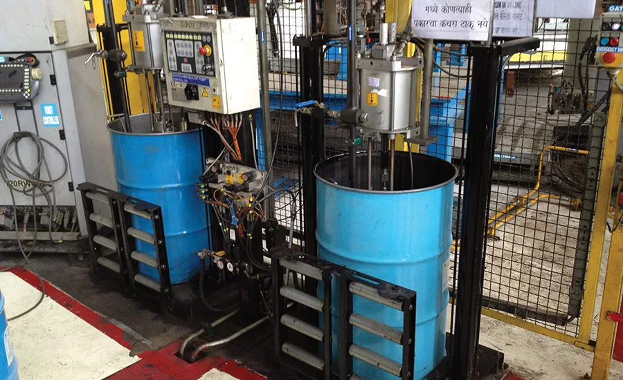
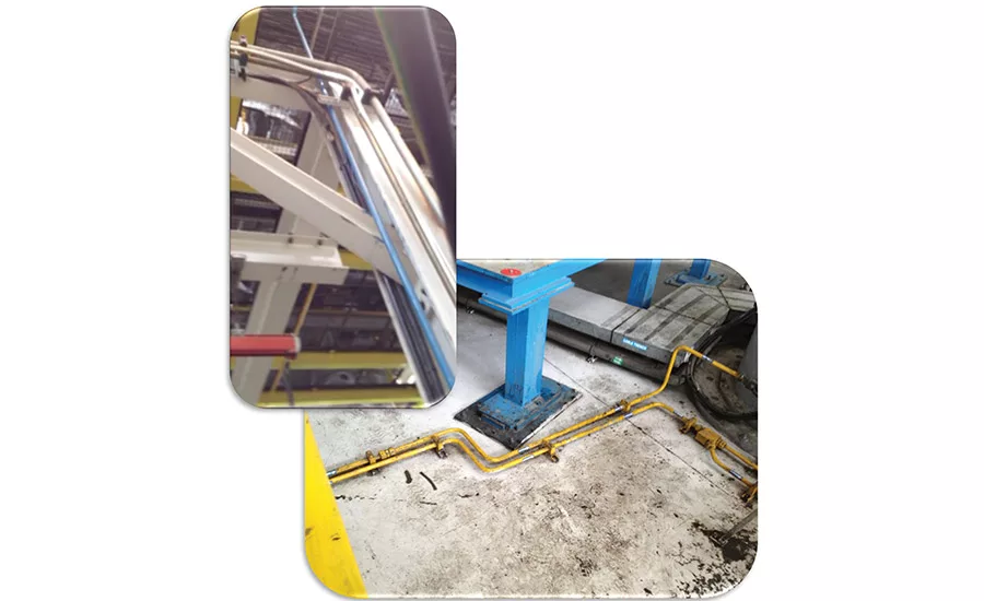
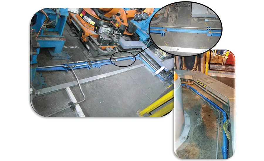
A systematic inspection of the system (see Figures 2-4) revealed that the header piping (starting from the pumping stations) and routing both overhead and along the floor (to the dispense cells) was all comprised of 25-mm (1-in.), uninsulated piping. These headers ranged from 20 m (65 ft) to 25 m (80 ft) in length. Because of these long distances, along with the high ratio of metal surface area-to-sealer volume, these headers were acting as heat exchangers, moving the temperature of the sealer toward plant ambient all along its path. This “heat exchanger” situation represented strong evidence that the changing temperature was the root of the issue.
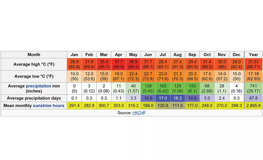
Located 145 km (90 m) southeast of Mumbai, Pune sits at an altitude of 559 m (1,863 ft). The weather varies significantly from winter to summer, with temperatures ranging from less than 10°C (50°F) to greater than 40°C (104°F), as shown in Figure 5. Not only does this represent season-to-season variation of up to 30°C (54°F), it also represents an average morning-to-night variation of as much as 20°C (36°F). The calculated dwell times for the various systems (the time that the sealer is in the header piping) ranged from just over 36 min to more than 100 min. This is all time that the sealer is changing temperature as a function of ambient―which is constantly changing as well. Moreover, this assumes that the line is running at full speed. Anything less than full speed means that the dwell time in the header increases.
The intermittent and unpredictable line shutdowns extend the dwell time, leaving more time to change the temperature. In short, under these conditions, the temperature of the sealer being delivered to the dispense system is in a constant state of change.
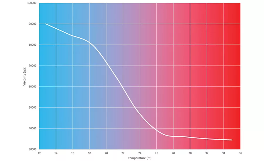
Why is this important? Because all liquids change viscosity as a function of temperature. The viscosity vs. temperature plot for a typical sealer is shown in Figure 5. When the sealer temperature increases, its viscosity decreases; conversely, when the sealer temperature decreases, its viscosity increases. From this, it is easy to understand that the variations in sealer temperature described previously will manifest in variations in sealer viscosity, which will result in variations in pressure drop throughout the delivery system. “But isn’t this common to all sealer systems?” you might ask.
The Common Solution
The answer is a qualified yes. Naturally, these parameters apply to all sealer dispensing systems, but many precautions can be used to mitigate them. To begin with, these systems are usually constructed with large headers, often 50 mm (2 in.), 75 mm (3 in.), or even 100 mm (4 in.) to reduce pressure drop in the long runs between the pumping stations and the application cells. The size selected is often determined by the length of the run and sometimes even the viscosity of the sealer being dispensed. Because the initial pressure drop is much lower in these larger headers, there is also less impact from the temperature-based changes in viscosity.
This is complemented by smaller drops to convey the material between the header and the application cells. The 25 mm (1 in.)
pipe used throughout the Pune system is a common choice for these drops. Their smaller cross-sectional area also tends to dampen the pressure variations in the main header ahead of the regulator.
Unfortunately, replacing the headers is a very expensive solution to retrofit into the existing system. First, there is the cost of materials like piping, fittings, etc. Then there is the labor to remove the existing headers and install the new ones. But one of the biggest costs in a project like this is the downtime required for implementation. This is non-productive time, in that production cannot continue while these changes are being made. Thus, it is non-revenue-generating time. Lastly, the disposal cost is significant; all of the old piping and sealer removed from the system must be properly disposed of.
A Better Alternative
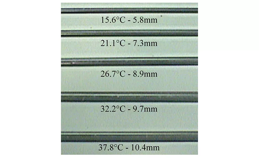
Since the root of this problem was temperature, the ability to control temperature offered an attractive alternative to explore. While robotic systems can repeat the gun path, speed, angle and distance to the part, flow rate, and total volume of sealer on every dispense cycle, they can’t compensate for the viscosity variations resulting from the ambient temperature swings that occur from morning-to-evening and season-to-season. Temperature-based viscosity variations directly affect the shape of the bead, as shown in Figure 6.
While the change in width of each bead is apparent, the height is not. Because each bead is comprised of the same volume of sealer, the change in width is offset by a change in height; the wider beads are also flatter. This is often referred to as “spread” or “slump” and can significantly compromise the function of the bead. It is essential to have exactly the right amount of sealer in exactly the right place with precisely the right profile to assure proper performance in the application.
Point-of-Application Temperature Control
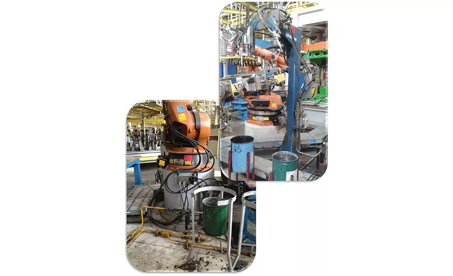
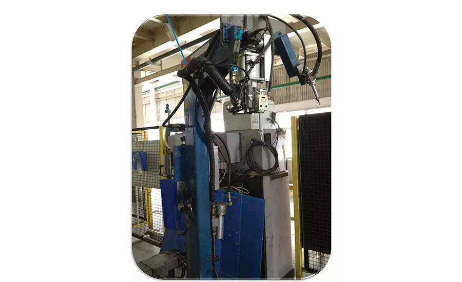
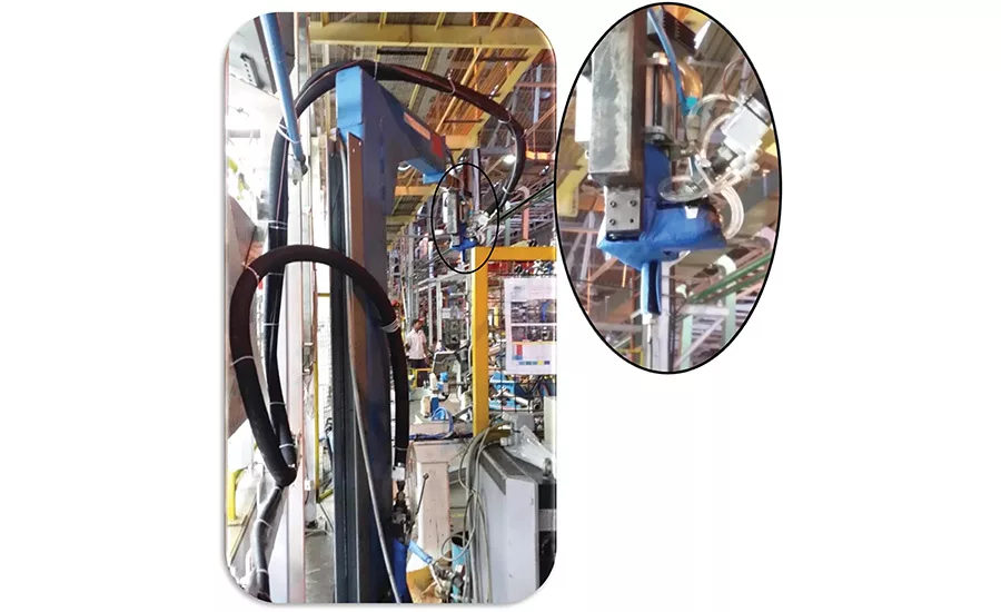
Figure 7 shows that, in order to produce the perfect bead with a robotic system, it is essential to dispense the sealer at exactly the right temperature. The best way to do that is by controlling the temperature as it is being dispensed. This is the point-of-application temperature control, which is often―but not always―the only place that matters.
For example, consider the sealer systems at Tata Motors. Figure 7 shows one of the pedestal systems. An electrically heated hose has been inserted between the filter outlet and the dispense gun inlet for the purpose of maintaining the temperature at the point of dispense. While one might question adding heat in an environment like India, this configuration would appear to be in keeping with the concept of point-of-application temperature control.
However, things are not always as straightforward as they seem. SCS defines the process for implementing point-of-application temperature control as follows:
1. Think backwards from everyone else.
2. Acknowledge that the only material of concern is that which is actually being applied to the part.
3. Start at the point-of-application.
4. Work backwards, adding temperature control until all ambient and process conditions can be met.
5. Stop.
While people often laugh at the first step, it is accurate in its simplicity. It is commonplace to start at the drum, adding thermal jackets or drum heaters in an attempt to control the temperature of the sealer. This neglects the thermal gains and losses incurred along the path to the point of dispense―usually with less-than-stellar results.
Where the original suppliers of this system went wrong is at Step 4. They added temperature control at (or near) the point of application, but they did not work backwards far enough to add sufficient temperature control to counteract all ambient and process conditions. The result was a continuous variation of sealer temperature (read: viscosity) that resulted in the pressure faults that kept shutting the line down. With that understanding, a cost-effective solution could be devised to address the root cause of the problem.
The Solution
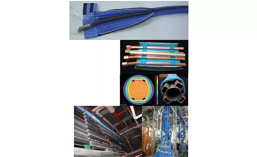
A combination of traced-cover and coaxial-hose technologies was designed to control the sealer temperature all along the delivery path, independent of variations in ambient temperature. As shown in Figure 8, the traced covers come in two basic forms: a soft, flexible version and a hard profile variety, but their fundamental principle of operation is the same.
The sewn cover is comprised of an outer layer of impregnated nylon rip-stop fabric covering a layer of Nomex insulation (originally developed for use in space suits). This isolates the device inside from the ambient environment.
In the flexible version, tube pockets are sewn to the inside and poly tubing is run through them to carry thermal conditioning fluid (usually water or glycol). This overcomes any loss through the cover insulation and creates a new ambient around the device it is covering at, or very near, the desired set point temperature. These are perfect for hoses and for piping runs (especially around corners). They can even be made in custom shapes to cover guns, valves, regulators, filters, and other devices in the material delivery path.
While the flexible traced covers are great for maintaining temperature in the system, the profile-traced covers are more active. In this configuration, the poly tubes and pockets are replaced with roll-formed copper profiles shaped to match the outside diameter of the fluid-carrying pipe. These conform to the outside of the pipe, and the metal-to-metal contact changes it into a tube-in-tube heat exchanger. These can be installed on straight runs of header without cutting into the pipe.
In each of these configurations, Velcro closures make installation easy. They can often be installed while the line is in operation, with little or no downtime at all.
Even with the headers controlled, maintaining point-of-application temperature requires conditioning between the header system and the gun—a job originally assigned to the electrically heated hose. But, with peak temperatures exceeding 40°C in Pune, there are obviously times where cooling is required to maintain a consistent, optimal sealer temperature. Since there is no way to cool with an electrically heated hose, it was removed to make way for a coaxial hose system.
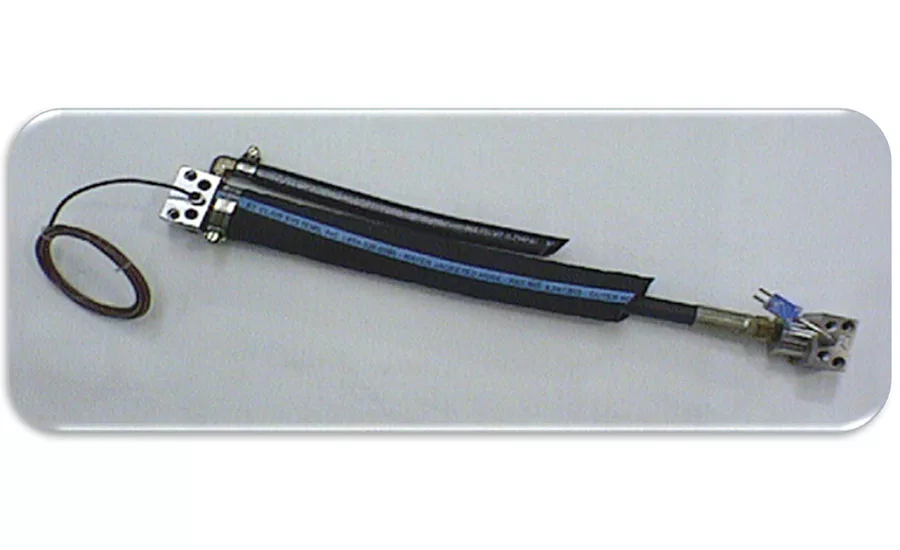
Figure 10 shows how this patented device is designed to act as a flexible tube-in-tube heat exchanger. In this configuration, the internal material-carrying hose is completely surrounded by the temperature-conditioned water circulating in the loop. In addition to routing the water, the block is designed with a port allowing the RTD to be placed directly into the material stream as it exits the hose, ensuring a stable temperature/viscosity at the point of application.
The Implementation
Each system started with a profile traced cover to bring the sealer to temperature as it entered the header. As shown in Figure 11,
additional lengths were distributed periodically throughout each header run, and these were joined with standard flexible traced covers to run around corners and clamps.
This system formed a temperature-controlled envelope around the entire length of the run, maintaining a constant sealer temperature (and thus constant viscosity) at all points along the path, independent of changes in ambient. This resulted in a stable and predictable pressure drop throughout the system.
With the header pressure drop stabilized, the next step was to control the temperature of the sealer at the point-of-application to assure consistent and repeatable dispense performance. As noted previously and shown in Figure 11, the electrically heated hose was replaced with a coaxial hose. This provided both heating and cooling capability for the sealer as it was conveyed to the gun. To complete the control envelope, a custom traced cover was made for the gun, again to isolate it from changes in ambient temperature. This controlled the temperature of the sealer all the way to the point of dispense, stabilizing sealer viscosity and allowing the dispense system to do its job effectively, efficiently, and repeatedly.
The Result
For each system, stabilizing the sealer temperature independent of swings in natural ambient resulted in a constant viscosity at all times throughout the material delivery system. This stabilized the pressure drop in the header system, allowing the pump to work at a constant output. Thus, virtually constant pressure was applied to the regulator, eliminating the pressure faults that were creating the line stoppages.
Likewise, the point-of-application tools put in place on each dispense system ensured that the temperature, and therefore the viscosity, supplied to the gun was also held constant. Because this temperature-controlled envelope was extended all the way to the nozzle, pauses between dispenses no longer created a drift in temperature in the gun and therefore each dispense became stable, uniform, and predictable. In short, better overall performance was achieved at a much lower cost than replacing the header systems. ASI
For more information, visit www.stclairsystems.com.
Looking for a reprint of this article?
From high-res PDFs to custom plaques, order your copy today!


