Vacuum Dispensing Helps Users Say Goodbye to Air Bubbles
Vacuum dispensing prevents air from getting caught between a component and coating.
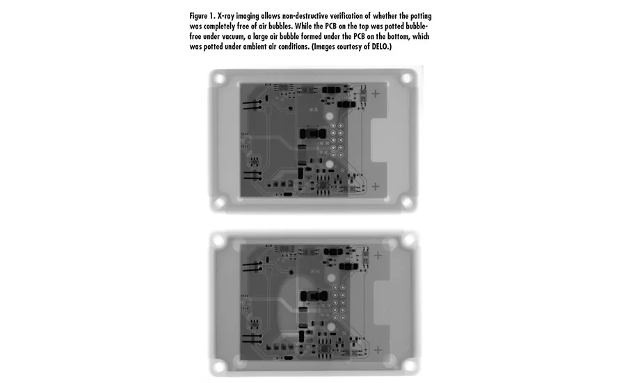
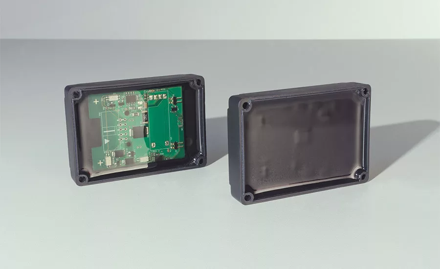
Figure 1. X-ray imaging allows non-destructive verification of whether the potting was completely free of air bubbles. While the PCB on the top was potted bubble-free under vacuum, a large air bubble formed under the PCB on the bottom, which was potted under ambient air conditions. (Images courtesy of DELO.)
When manufacturing electronic components, it is important to protect the workpieces against future external influences; most manufacturers use potting or filling to do this. Vacuum dispensing is often the method of choice, especially for high-performance applications. While many manufacturers use this highly efficient type of dispensing, others have not tried it because they consider it too complex, or they think the up-front investment is too high.
Sensitive Electronic Components
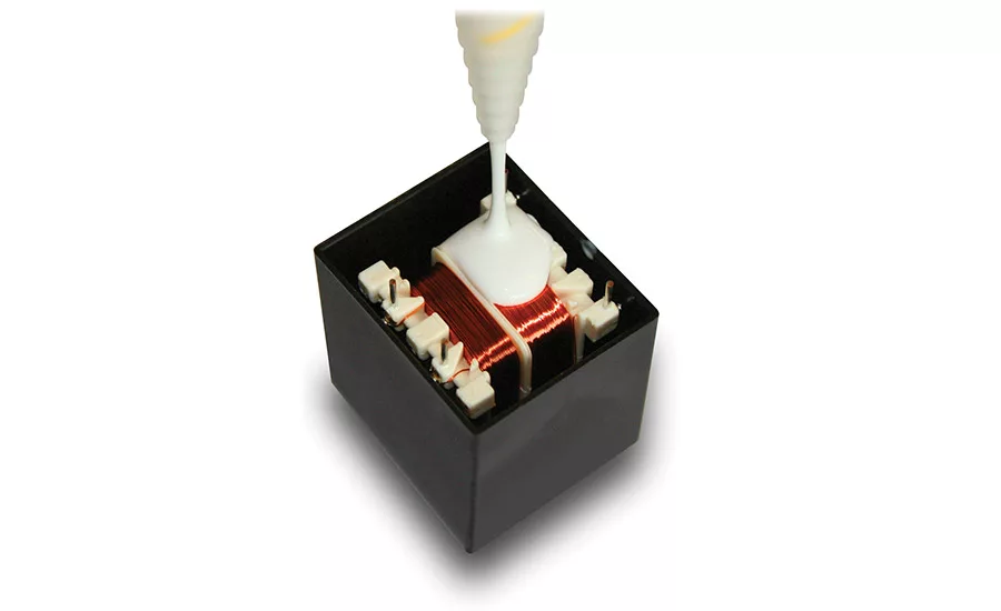
Automotive, industrial and consumer electronics all comprise electronic components such as chips or entire printed circuit boards (PCBs) that must be protected against mechanical or chemical stress. One typical example are motor control sensors such as exhaust sensors or components that come in contact with hot gearbox oil. Other applications involve unprotected wire coils and the enameled copper wires of wire coiled components. Depending on their usage, any one of these components may be exposed to considerable stress in terms of corrosion, vibrations, moisture or high voltage. Since injection molding is a highly complex production technique and production costs of the molds are considerable, most manufacturers choose potting or filling for their production environment.
However, conventional metering and dispensing methods often do not cover all requirements. For example, the tiny gaps between coiled wires may trap air bubbles, which break the insulating cover and diminish or even ruin high-voltage resistivity. Air bubbles caught below PCBs expand when heated—by several mm if the geometry allows—which causes tensile loads to act on the coating and on the PCB. In this case, high voltage surges may rupture the coating even if flexible and voltage resistant adhesives are used. Aggressive chemicals such as oil may come into contact with the unprotected surface and damage the component.
The Solution for Demanding Cases
Vacuum dispensing can solve these issues, especially in the production of high-performance electronic assemblies. The dispensing method—also suitable for in-line integration—produces a vacuum of 1 mbar or less if required, which prevents air from getting caught between component and coating. Vacuum dispensing is not only ideal for expensive high-voltage parts and safety-related components, it also handles assemblies with complex geometries, undercuts, or extremely narrow gaps.
In addition to the functional aspects, vacuum dispensing may also be an interesting method from a design point of view. For example, the often-complex shapes of flared side skirts or the production of illuminated buttons and switches place higher demands on the production technology used. As these parts are always in direct view of their users, even the tiniest inhomogeneities and air bubbles in these design pieces and components will render them rejects. Vacuum dispensing in these cases allows results that yield high-quality appearance and texture—an advantage that other dispensing methods only achieve at very high costs, if at all.
From a technical standpoint, the generation of a perfect vacuum that is entirely void of air is not required. Vacuum in this context means the reduction in pressure down to approximately 1 mbar. The further the air pressure is reduced, the longer the process takes and the higher the energy costs rise. In addition, not every component can sustain a strong pressure reduction, which is a fact to bear in mind when applying a vacuum. While wire coiled components are mostly insensitive to atmospheric pressure, air encapsulated within a capacitor can cause the component to burst when exposed to an external vacuum. Therefore, the vacuum level should always be matched to the task at hand.
To guarantee that no bubbles are introduced, the complete preparation, feeding and metering process must be carried out in a vacuum. A process called thin-film degassing performed by a high-end material preparation and processing system then removes all traces of dissolved air. An agitator is used to further speed up the degassing process by stirring and circulating the dispensing material. This lets all of the contained air rise to the surface of the material, where it comes into contact with the surrounding vacuum. The degassing effect occurs at the surface layers of the material. In order to prevent air from re-entering the material during material reloading, all fittings, material feed lines, pumps and valves are sealed air-tight.
The agitator and a well-timed circulation of the material in tanks, pumps and feed lines keep the dispensing medium homogeneous at all times. This prevents sedimentation of the contained filler materials, which can easily occur during production breaks. For practical purposes, it proved helpful to design dispensing systems specifically for abrasive media. These systems allow the processing of dispensing materials that contain hard and abrasive fillers. As they are purpose-built for the task, they run efficiently at low maintenance and servicing costs.
Comparison Test
In order to demonstrate the difference between vacuum and atmospheric-pressure dispensing to manufacturers debating using vacuum dispensing systems, DELO Industrie Klebstoffe and Scheugenpflug set up a test system made of standard equipment. They used a conventional PCB in a standard PBT plastic housing as the substrate, and a low-viscosity two-component acid anhydride epoxy resin as the potting resin to simulate a common automotive application. The resin is specifically designed for high-performance applications and provides long-lasting temperature stability up to 200°C. It is resistant against diesel, gasoline and oil, and protects motor and exhaust control sensors during engine operation.
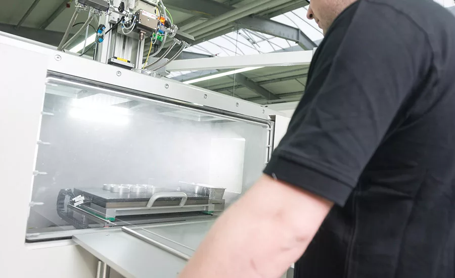
The test potting under ambient air conditions was carried out with the two components manually mixed and metered. For the vacuum test run, the dispensing material was degassed and then metered and dispensed. To obtain a laboratory-scale setup, we used the Scheugenpflug LeanVDS system, a typical entry-level model for vacuum dispensing. This compact-sized system is best suited for R&D applications, for small batch production, and to replace inaccurate or time-consuming auxiliary processes such as post-evacuation.
In order to analyze the test results, DELO and Scheugenpflug used X-ray scans. As opposed to microsections, this test method is non-destructive and has the additional benefit of making sure that no air bubbles are overlooked if the section was made at a position that just happened to be free from bubbles. When comparing the X-ray images of the two components, distinct differences immediately became evident (see Figure 1). While the PCB on the left was potted bubble-free under vacuum, a large bubble of air had formed under the PCB on the right, which was potted under ambient air conditions. What does that mean? Depending on how the component is used later and on its operating environment, the component is very likely to fail—even if this might take several months or sometimes even years.
Finding the Right Combination
Depending on the dispensing system used, bubbles can easily form during preparation, feeding and delivery, or while mixing one- or two-component dispensing materials. Large inclusions of air prove even more fatal to the reliable functioning of electronic assemblies or the visual high-quality appearance of exclusively shaped design parts. These tend to occur near undercuts or in components where production conditions require them to have complex geometries. By combining the right dispensing material with an all-in-one vacuum dispensing, preparation and feeding system, manufacturers have all the instruments they need to increase their components’ reliability to an extent where they comply with all necessary thermal, mechanical, chemical, and design requirements.
For more information, visit www.scheugenpflug-usa.com.
DELO can be found online at www.delo-adhesives.com.
Looking for a reprint of this article?
From high-res PDFs to custom plaques, order your copy today!


